Login
You are currently not logged in! Enter your authentication credentials below to log in. You need to have cookies enabled to log in.
Omnicomm Profi 3.0
Prerequisites
Connectivity
Configuration
Network
LLS
RPM
Universal Inputs
CAN bus
Omnicomm Optim 3.0
Prerequisites
Connectivity
Configuration
Network
LLS
RPM
Universal Inputs
CAN bus
Omnicomm Profi Wi-Fi 3.0
Prerequisites
Connectivity
Configuration
Network
LLS
RPM
Universal Inputs
CAN bus
Teltonika FMC125
Prerequisites
qwerty 123
Connectivity
Configuration
Network
LLS
RPM
Universal Inputs
CAN bus
Teltonika FMC650
Prerequisites
Step 1: Install Software
- Download & install Teltonika Configurator for your OS:
- Install COM Port Drivers for PC communication:
Connectivity
Step 2: Fuel Sensor Connection
FMC 650 MOUNTING RECOMMENDATIONS
CONNECTING WIRES
- Wires should be fastened to the other wires or non-moving parts. Try to avoid heat emitting and moving objects near the wires.
- The connections should not be seen very clearly. If factory isolation was removed while connecting wires, it should be applied again.
- If the wires are placed in the exterior or in places where they can be damaged or exposed to heat, humidity, dirt, etc., additional isolation should be applied.
- Wires cannot be connected to the board computers or control units.
CONNECTING POWER SOURCE
- Be sure that after the car computer falls asleep, power is still available on chosen wire. Depending on car, this may happen in 5 to 30 minutes period.
- When module is connected, measure voltage again to make sure it did not decrease.
- It is recommended to connect to the main power cable in the fuse box.
- Use 3A, 125V external fuse.
CONNECTING IGNITION WIRE
- Be sure to check if it is a real ignition wire i. e. power does not disappear after starting the engine.
- Check if this is not an ACC wire (when key is in the first position, most of the vehicle electronics are available).
- Check if power is still available when you turn off any of vehicles devices.
- Ignition is connected to the ignition relay output. As alternative, any other relay, which has power output when ignition is on, may be chosen.
CONNECTING GROUND WIRE
- Ground wire is connected to the vehicle frame or metal parts that are fixed to the frame.
- If the wire is fixed with the bolt, the loop must be connected to the end of the wire.
- For better contact scrub paint from the spot where loop is going to be connected.
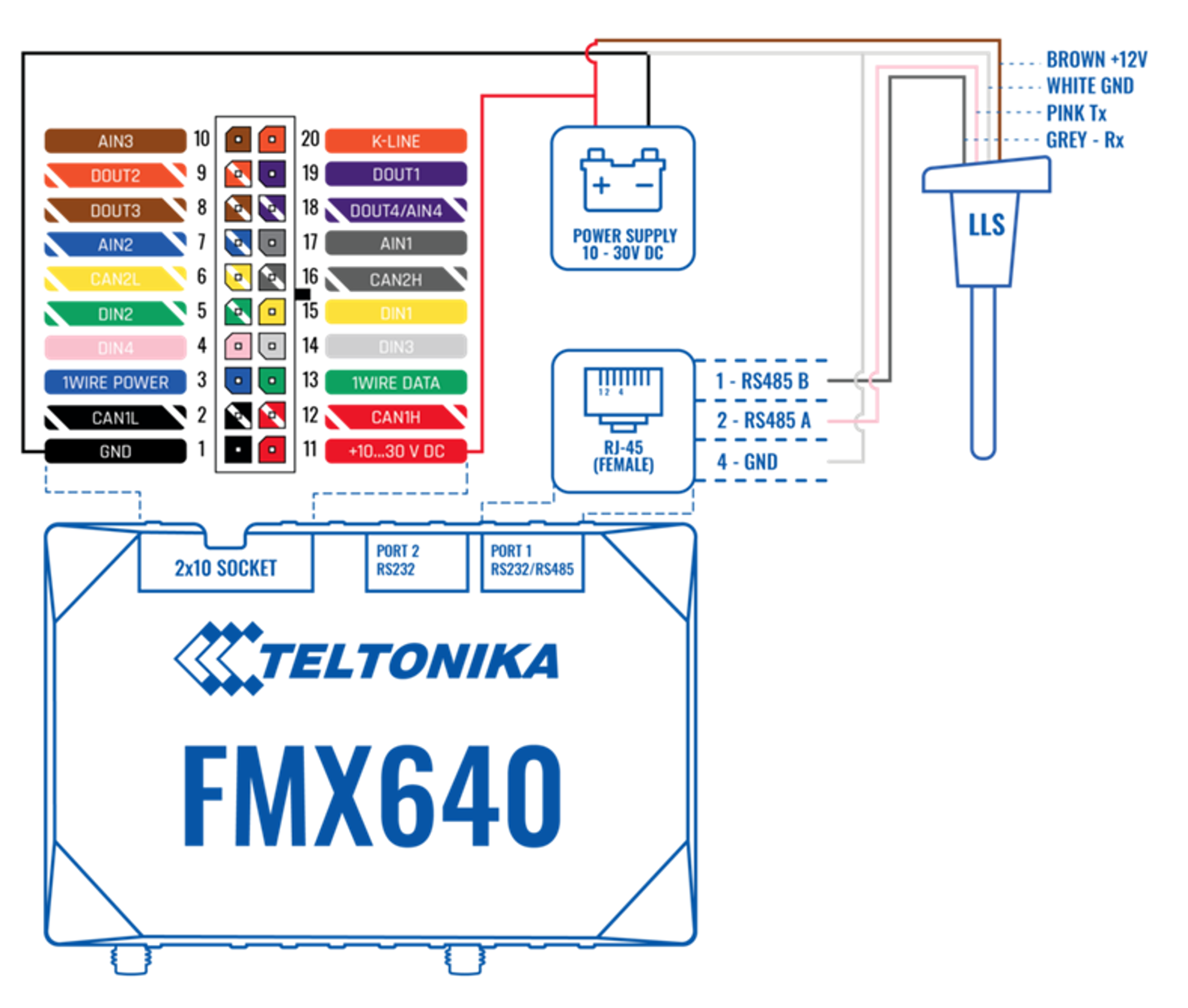
Connect Omnicomm LLS sensors to the RS485 (RJ45) port using the appropriate connector.*
*A cable with an RJ-45 connector is not included in the FMC650 delivery pack.
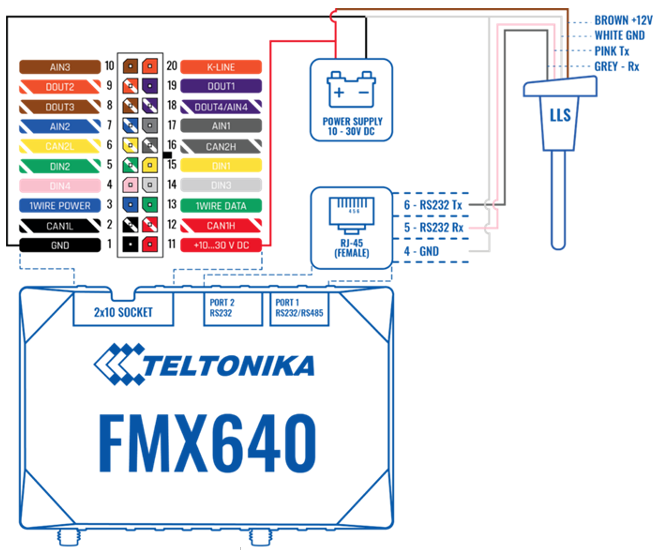
RS232 Digital Sensor Connection
Step 3: Connect FMC650 Tracker
3. Use the USB/2-USB cable or another suitable cable to connect the FMC650 tracker to your PC.*
*A cable with an USB/2-USB connector is not included in the FMC650 delivery pack.
4. Open Teltonika Configurator and wait for it to detect the connected device (1- 2 min). The configurator could restart after the recognition tracker.
Step 3: Network Configuration
5. When your device appears, enter the configuration window. 6. Go to the “System” tab.
 Set ignition input:
   * The ignition wire must be connected to **AIN1 input**.
   * Under Ignition Source, select the corresponding **AIN1 flag**.


