Login
You are currently not logged in! Enter your authentication credentials below to log in. You need to have cookies enabled to log in.
Omnicomm Profi 3.0
Omnicomm Optim 3.0
Omnicomm Profi Wi-Fi 3.0
Teltonika FMC125
Step 1: Install Software
1. Download & install Teltonika Configurator for your OS:
2. Install COM Port Drivers for PC communication:
Mounting
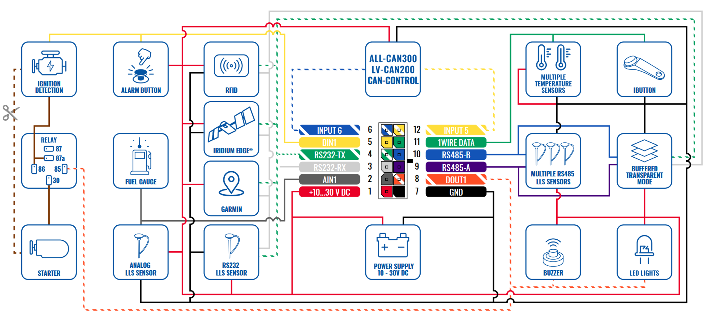
Step 2: Fuel Sensor Connection
FMC 125 MOUNTING RECOMMENDATIONS
CONNECTING WIRES
- Wires should be fastened to the other wires or non-moving parts. Try to avoid heat emitting and moving objects near the wires.
- The connections should not be seen very clearly. If factory isolation was removed while connecting wires, it should be applied again.
- If the wires are placed in the exterior or in places where they can be damaged or exposed to heat, humidity, dirt, etc., additional isolation should be applied.
- Wires cannot be connected to the board computers or control units.
CONNECTING POWER SOURCE
- Be sure that after the car computer falls asleep, power is still available on chosen wire. Depending on car, this may happen in 5 to 30 minutes period.
- When module is connected, measure voltage again to make sure it did not decrease.
- It is recommended to connect to the main power cable in the fuse box.
- Use 3A, 125V external fuse.
CONNECTING IGNITION WIRE
- Be sure to check if it is a real ignition wire i. e. power does not disappear after starting the engine.
- Check if this is not an ACC wire (when key is in the first position, most of the vehicle electronics are available).
- Check if power is still available when you turn off any of vehicles devices.
- Ignition is connected to the ignition relay output. As alternative, any other relay, which has power output when ignition is on, may be chosen.
CONNECTING GROUND WIRE
- Ground wire is connected to the vehicle frame or metal parts that are fixed to the frame.
- If the wire is fixed with the bolt, the loop must be connected to the end of the wire.
- For better contact scrub paint from the spot where loop is going to be connected.
Step 3: Connect FMC125 Tracker
3. Use the micro USB-USB cable or another suitable cable to connect the FMC125 tracker to your PC.*
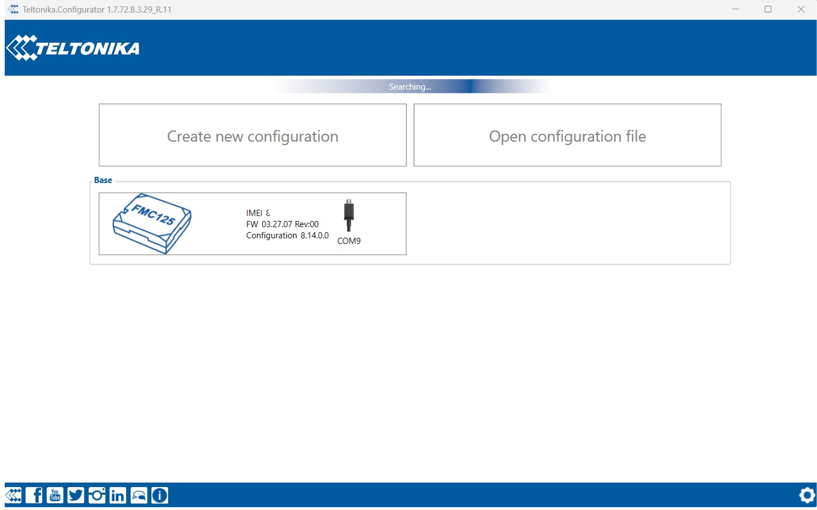
4. Open Teltonika Configurator and wait for it to detect the connected device(1- 2 min). The configurator could restart after the recognition tracker.
Configuration
Step 4: Network Configuration
5. When your device appears, enter the configuration window.
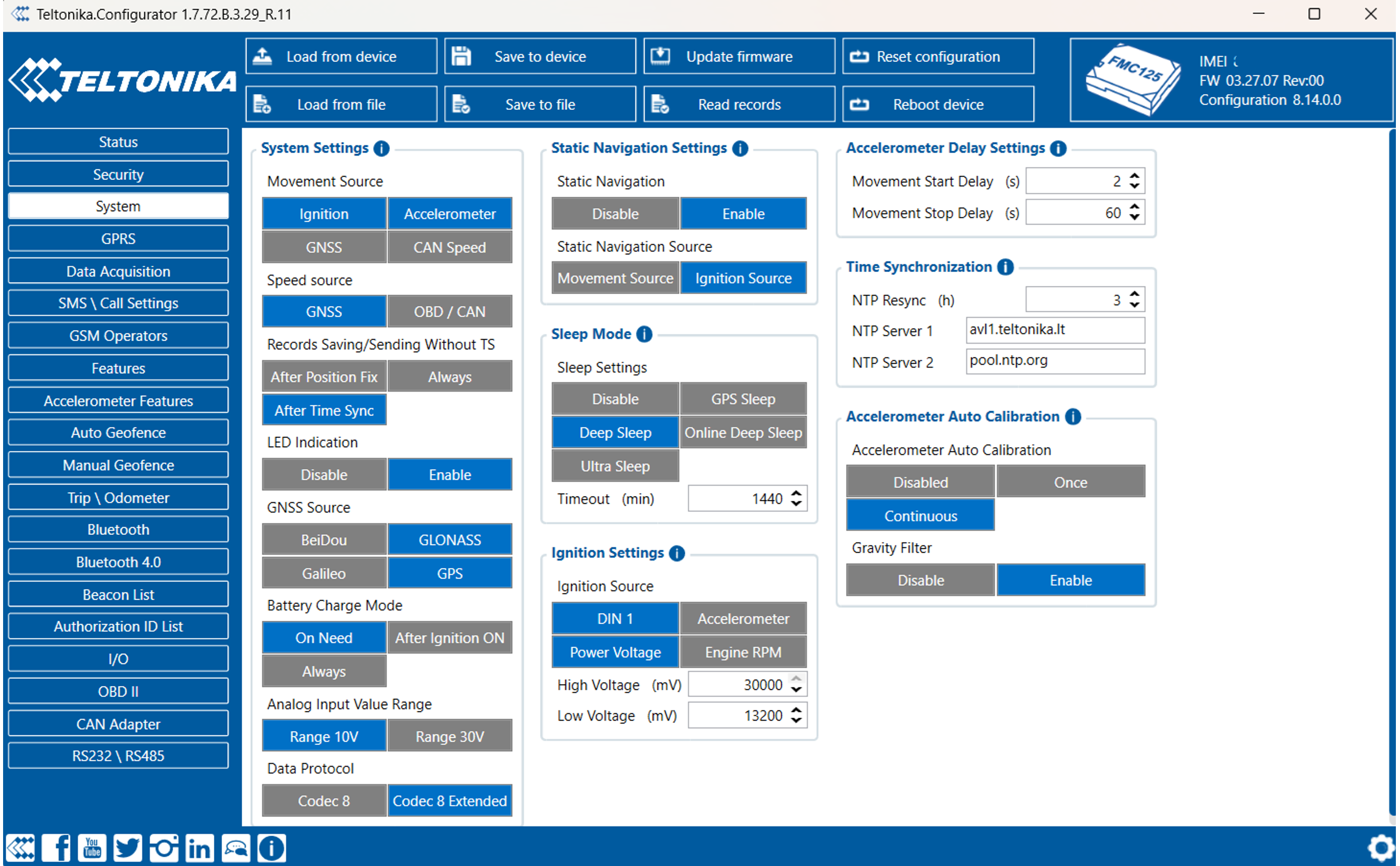
6. Go to the System tab.
Set ignition input:
- The ignition wire must be connected to AIN1 input.
- Under Ignition Source, select the corresponding AIN1 flag.
Under Data Protocol, select one of the following:
- Recommended: Codec 8 or Codec 8 Extended
- Note: Choosing a protocol defines which port you'll configure in the GPRS tab.
Under Records Settings set Sort by: Oldest
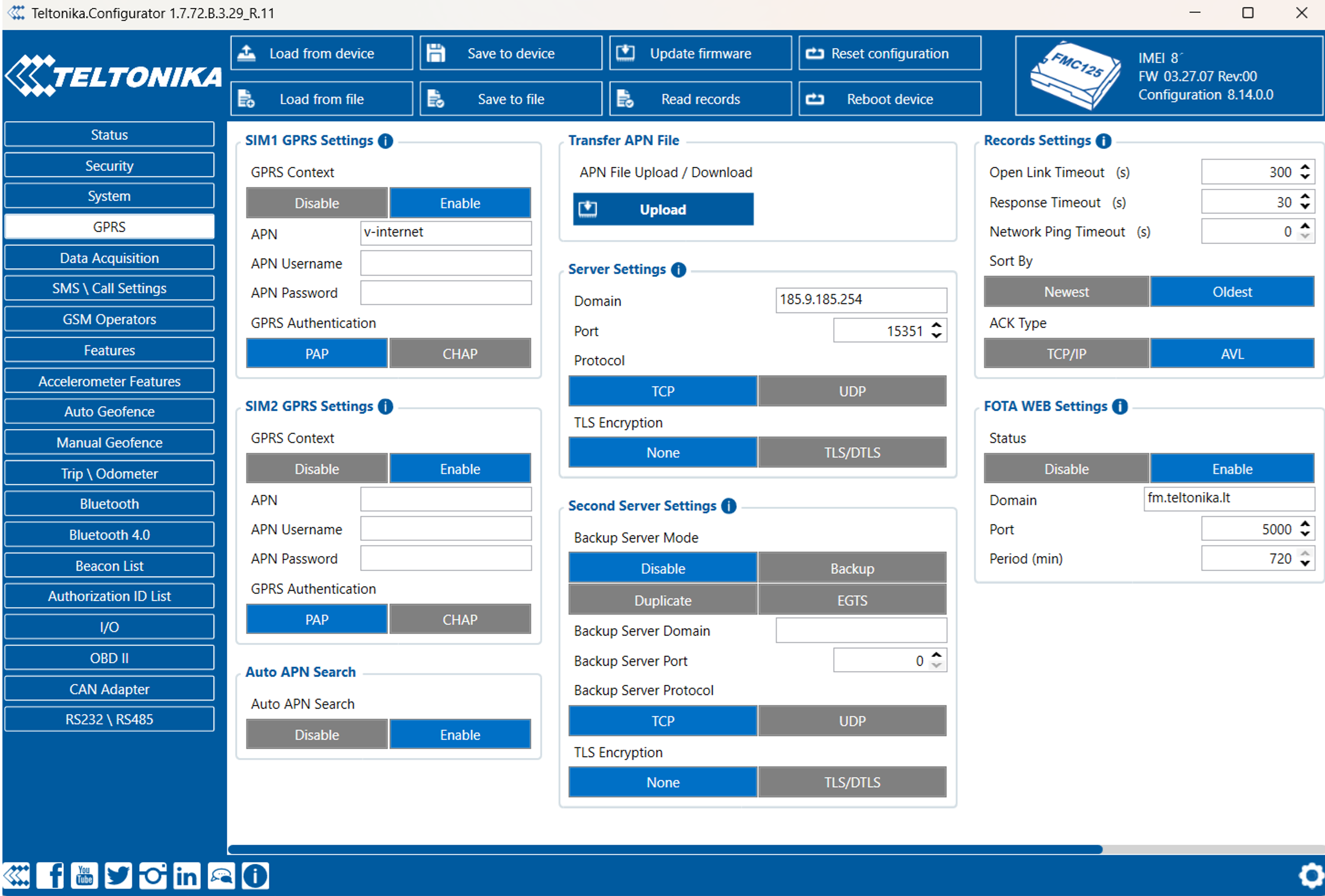
10. Go to the GPRS tab.
Configure APN and password if required by your SIM card provider.
Under Server Settings, enter:
- Domain: 185.9.185.254 or convert.omnicomm.ru
- Port:
  Codec 8: 15350
  Codec 8 Extended: 15351
  Codec 8 Professional: 15352
  Codec 8 Professional Extended: 15353
13. Protocol: TCP.
14. Under Records Settings
- Set Sort by: Oldest
Step 4: LLS sensors Settings
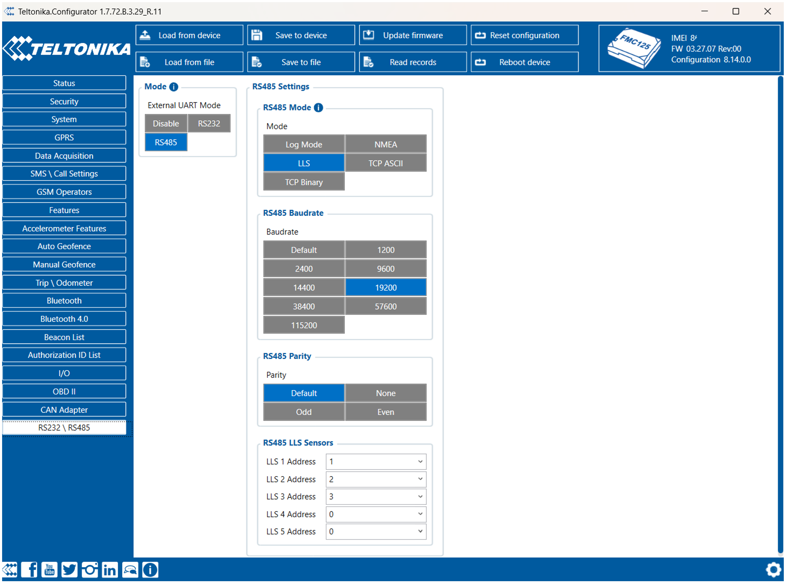
RS485:
16. Open the RS232/RS485 tab.
17. Under RS485 Settings:
- RS485 Mode: LLS
- Baudrate: 19200 (must match sensor setting)
18. Under RS485 LLS Sensors:
- Set LLS 1 Address: 1
- Set LLS 2 Address: 2, etc.*
- (Sensor IDs must match the ones configured on the LLS sensors.)
*FMC125 supports connection up to 5 digital sensors through RS-485
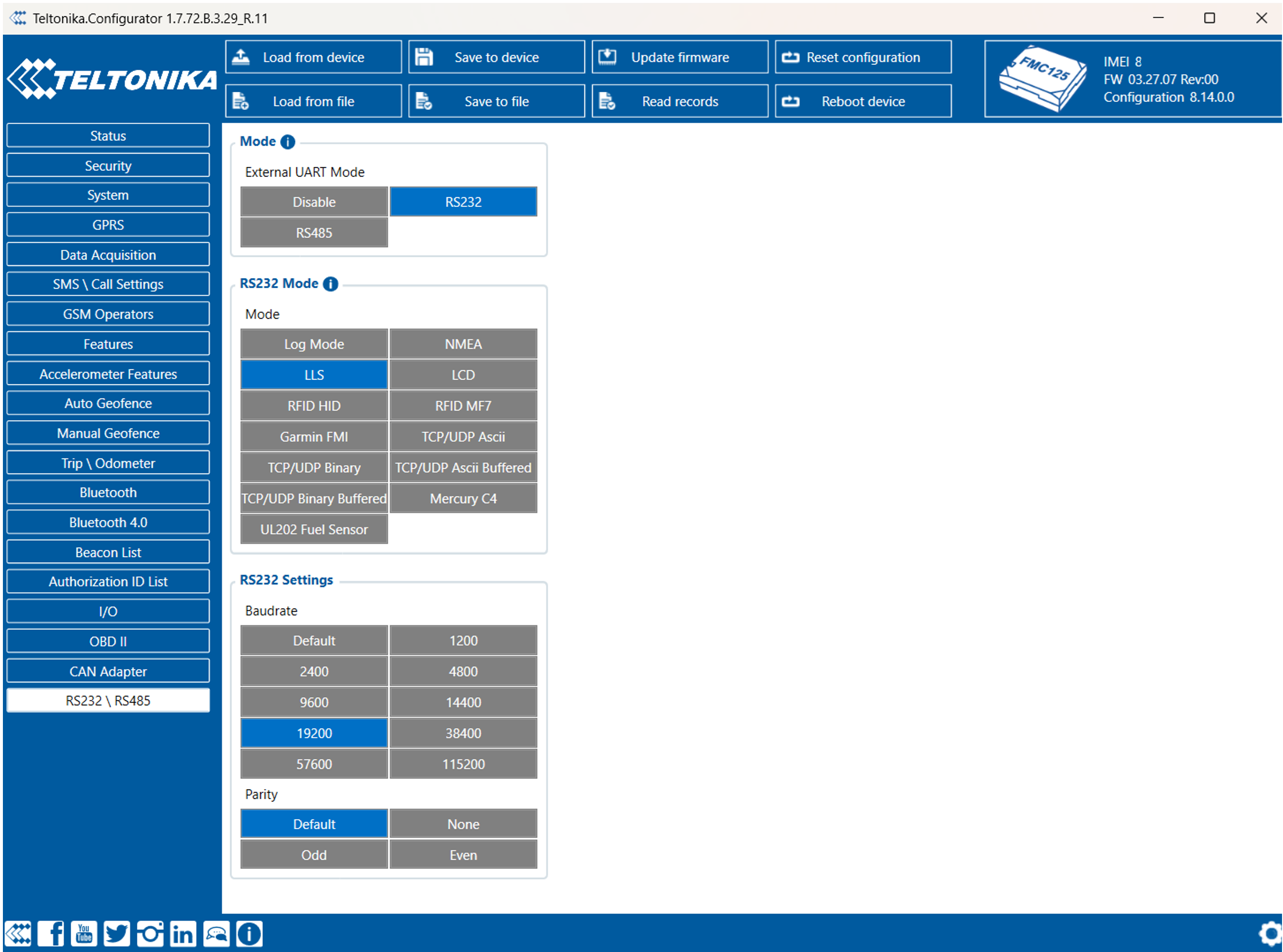
RS232:
19. Under RS232 Settings:
- COM 1 or COM 2 Mode: LLS
- Baudrate: 19200
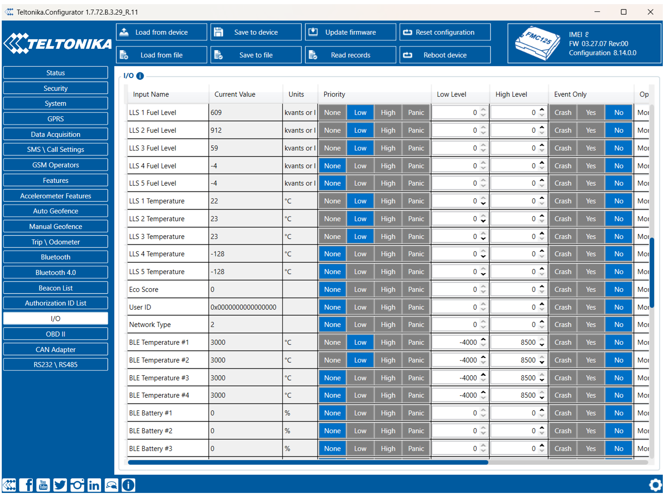
Go to the I/O tab.
Set the priority of:
- LLS 1 Fuel Level – LLS 6 Fuel Level (must match sensors number)
- LLS 1 Temperature – LLS 6 Temperature (must match sensors number)
- Set each of these to LOW priority
In case of use Digital or Analog inputs, set the priority and range accordingly.
Step 5: Verify Readings
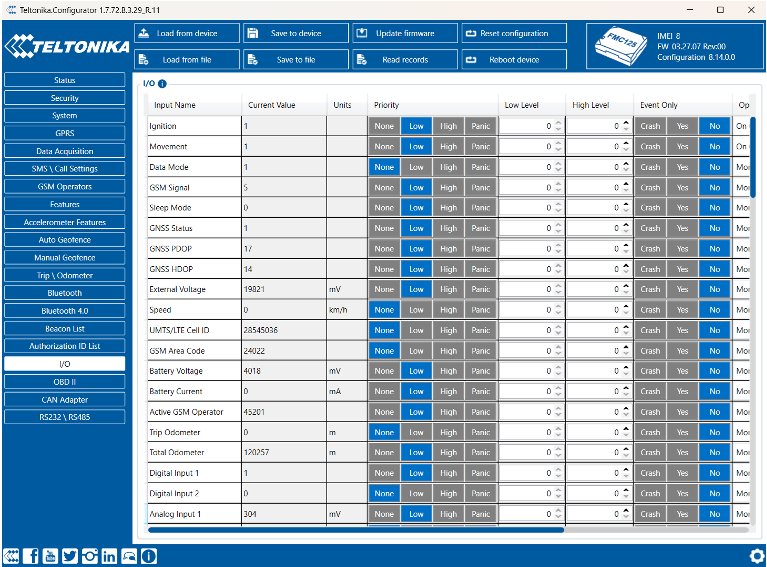
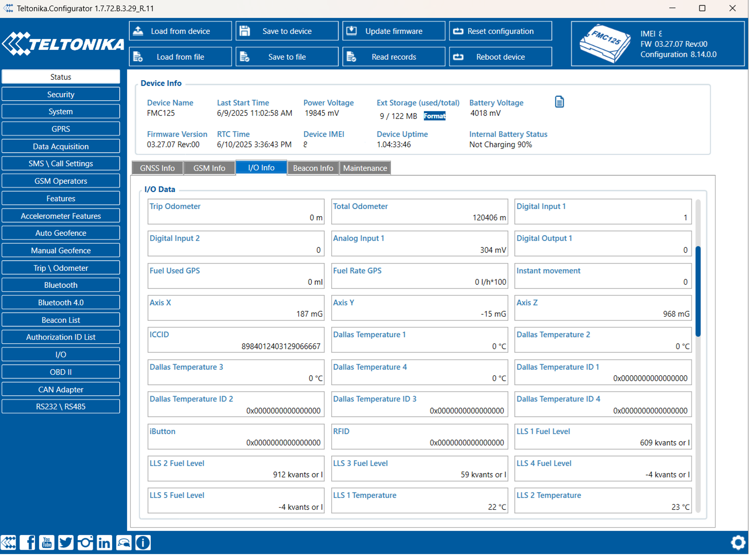
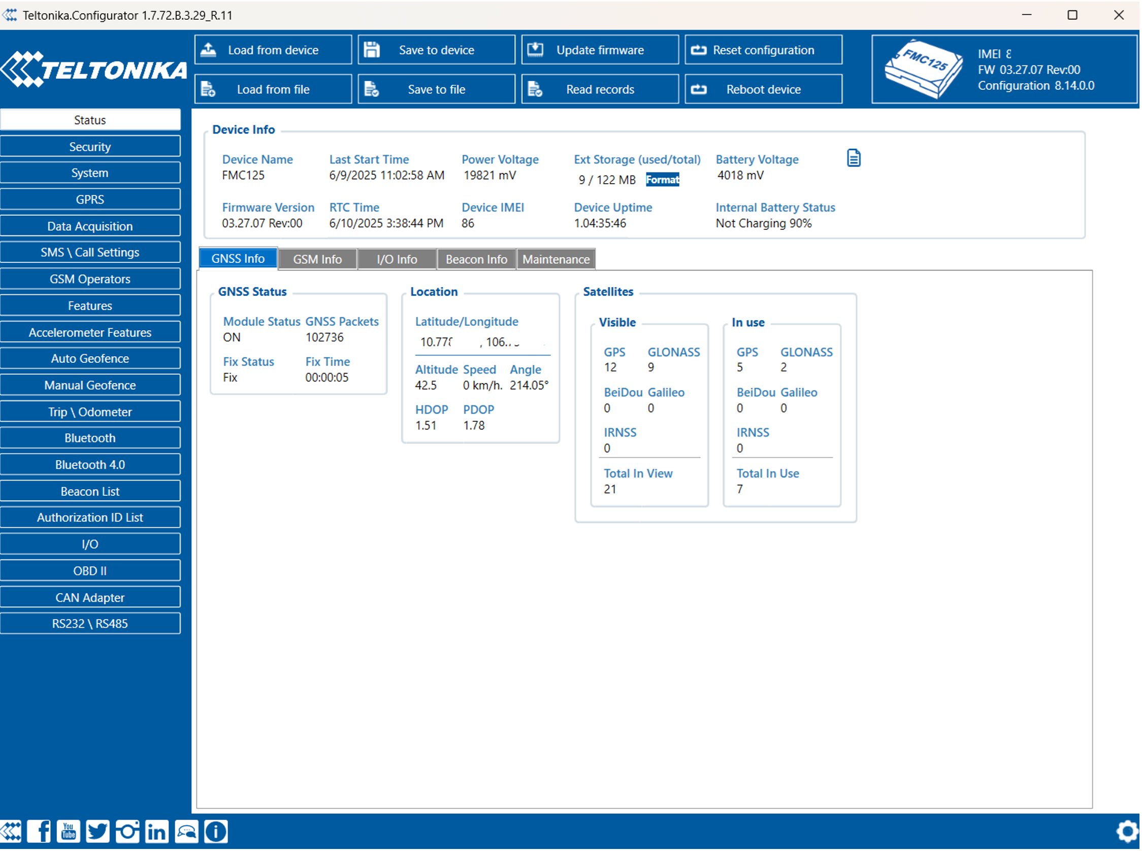
22. Go to the Status tab to confirm data:
- Check the I/O tab.
- Check GNSS info.
- Check GSM info to verify SIM/network connection and server data transmission.
Profile Setup
Step 6: Add VH and verify Readings on the platform
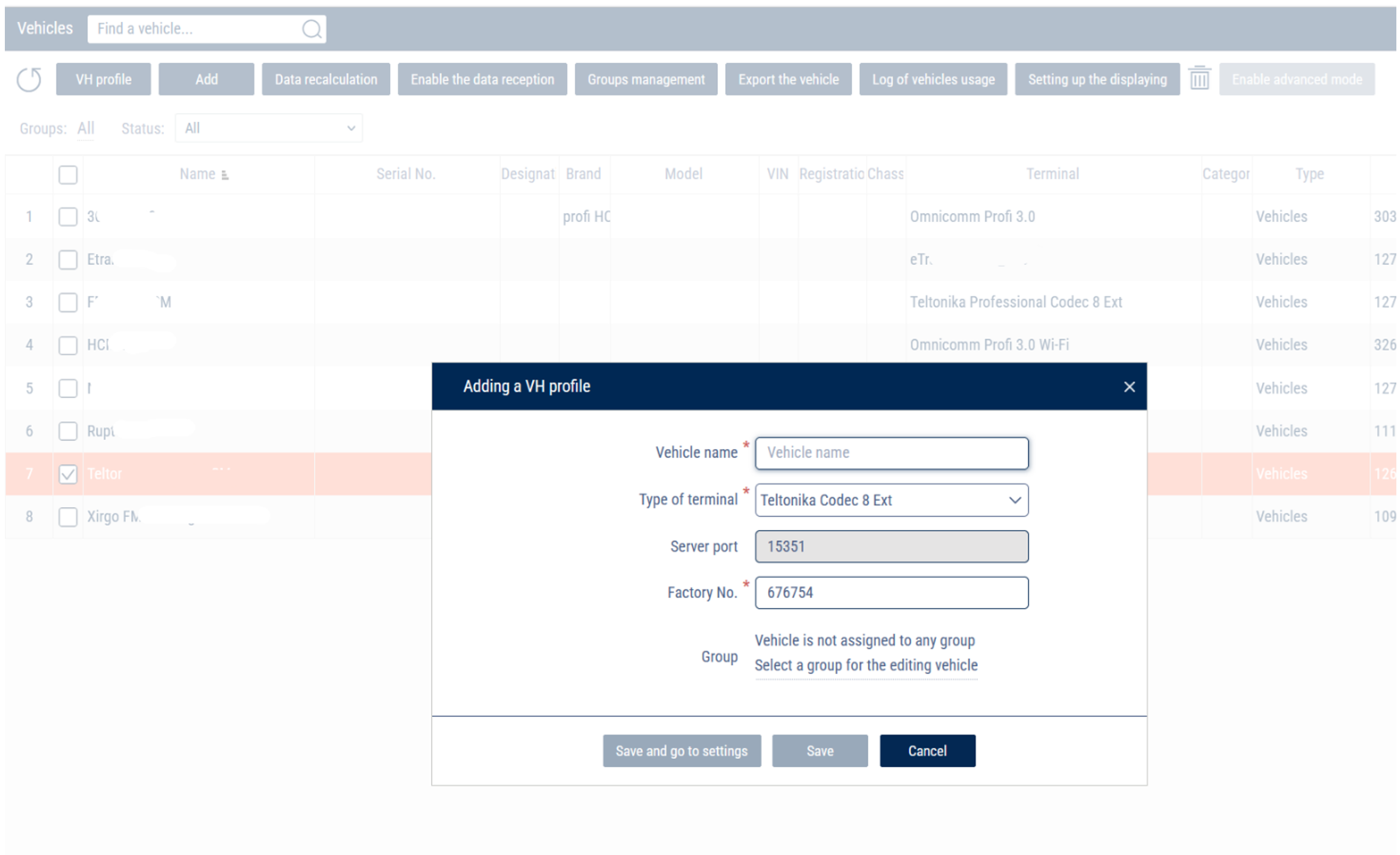
23. Log in to your account and open Administration Vehicles tab
- Click Add.
- Choose Type of terminal: Teltonika Codec 8 Ext
- Server port will set automatically 15351 (must fit server port in GPRS tab)
- Put your device's IMEI number in Factory No. field
- Put the name in Vehicle Name field (this name will be displayed in reports)
24. Click on created VH in the list and click VH Profile button.
- Open Profile tab set up settings according manual: https://doc.omnicomm.ltd/en/omnicomm_online-administration/vehicle/add/profile_settings
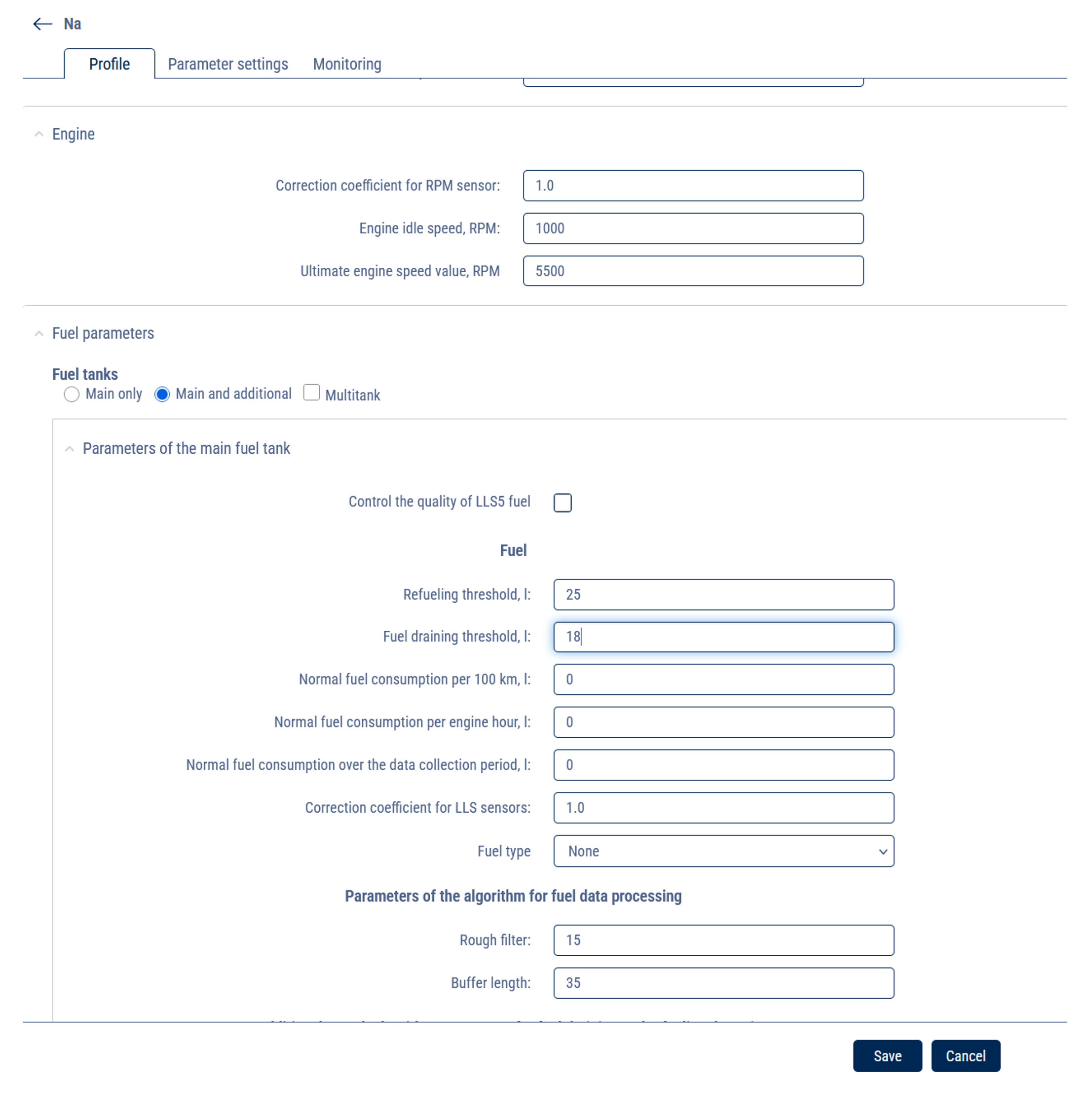
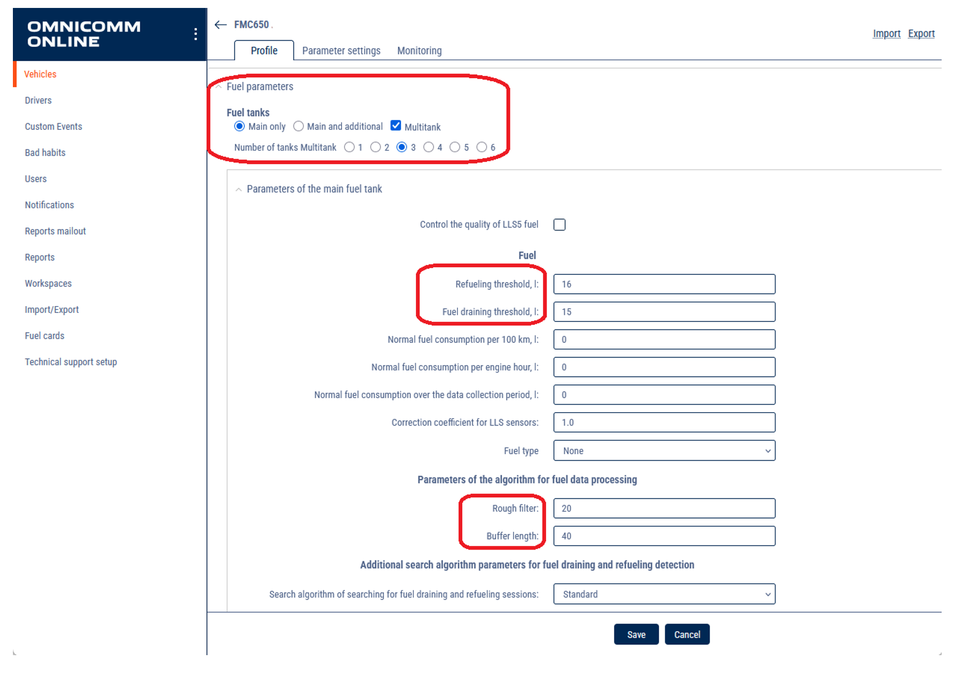
- In the Fuel parameters section, choose a number of tanks and number of installed LLS.
- Fuel tanks - select the number of fuel tanks installed on a vehicle:
Main only means only one fuel tank is installed on a vehicle
Main and additional means two fuel tanks are installed on a vehicle. For refuellers, the main tank is the reservoir, the additional tank is the engine fuel tank. For the vehicle, the main tank is the engine fuel tank, the additional tank is the fuel tank for the optional equipment.
Multitank means up to 6 fuel tanks are installed on a vehicle. Available to users with established rights to objects: Access to Multitank (see Adding and editing a user profile).
Examples:
- Main tank and single sensor: Common scenario.
- Main tank and 2 sensors and more: In case of a complicated shape or impossibility to install a sensor in the center, two or more sensors are used for measurement level in a single tank.
- Main and additional tank and 2 sensors: A Vehicle has 2 tanks, and each tank is equipped with 1 sensor.
- Main and additional tank and 3 or more sensors: A Vehicle has 2 tanks, and each tank is equipped with 1 or more sensors.
- Main tank + Multitank or Main and additional tank + Multitank is scenarios for fuel bowser, gas stations e.t.c. For each cistern or isolated compartment could be assigned one or several sensors.
For each tank set up Parameters of the fuel tank:
- Set up Refueling threshold (recommended value 7% of tank volume, number depends on condition);
- Set up Fuel draining threshold (recommended value 7% of tank volume, number depends on condition);
- Set up Rough filter (depends on road condition);
- Set up Buffer length (depends on road condition);
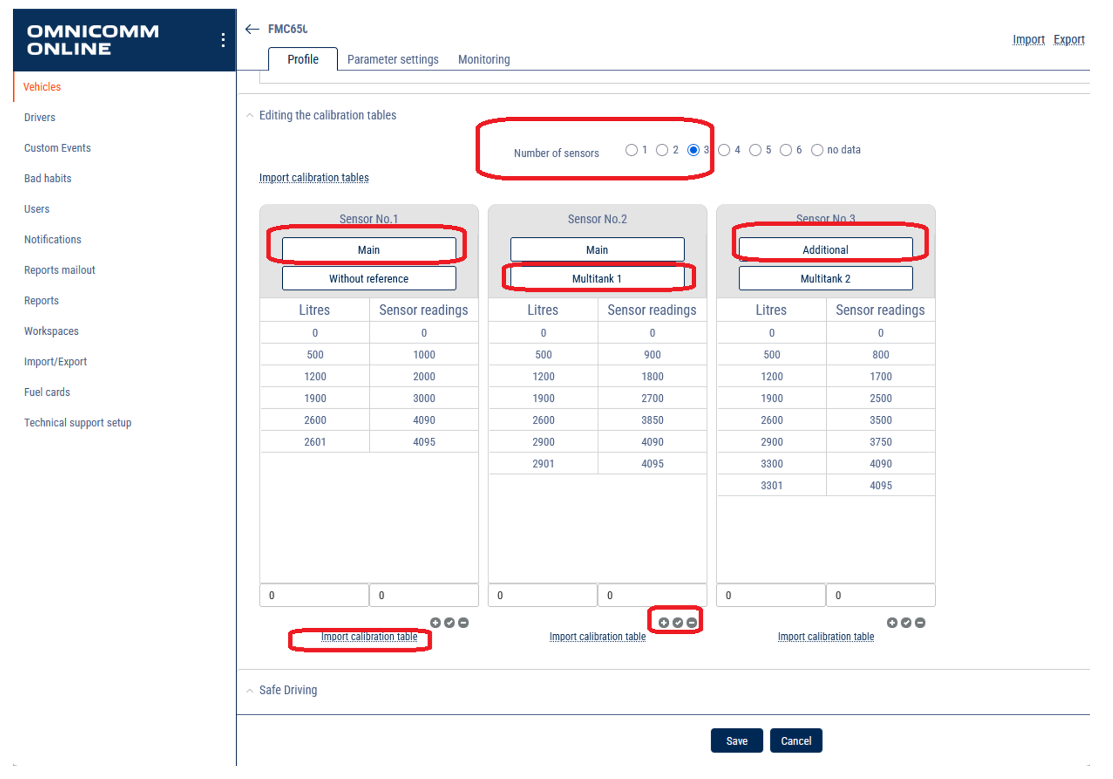
- In Editing the calibration tables, import calibration tables or fill it manually and link sensors to the tanks.
25. Open Parameter settings tab:
- Choose and link the necessary parameters.
- For CHECK FUEL LEVEL SENSOR choose source of data for each LLS:
For Fuel level sensor 1:
- Calculation method: LLS1 Level
- Determining method for the fuel level sensor condition: Calculate
- Level is 0: Mode = Ready
- Level above 4095: Mode = Error
- Fuel temperature Calculation method: LLS1 Temperature
For Fuel level sensor 2:
- Calculation method: LLS2 Level
- Determining method for the fuel level sensor condition: Calculate
- Level is 0: Mode = Ready
- Level above 4095: Mode = Error
- Fuel temperature Calculation method: LLS2 Temperature
Same for each sensor.
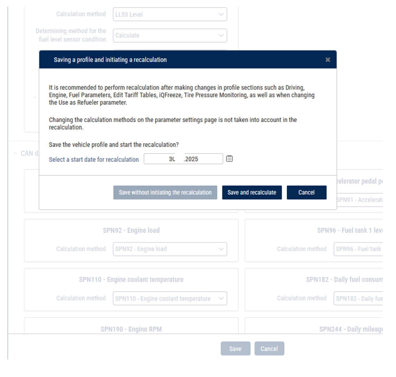
- Click Save and recalculate.
- Choose VH in the list and click VH Profile button.
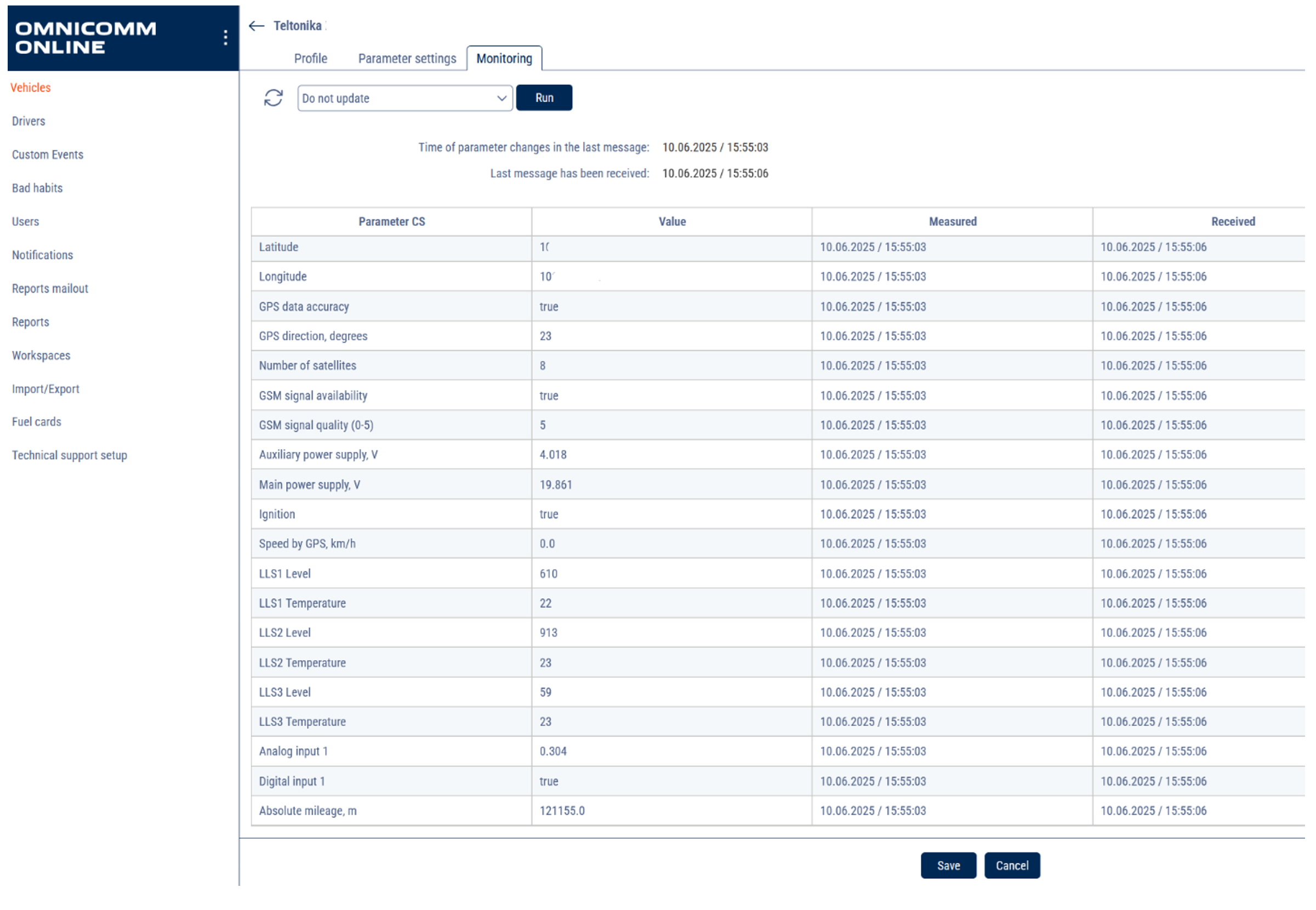
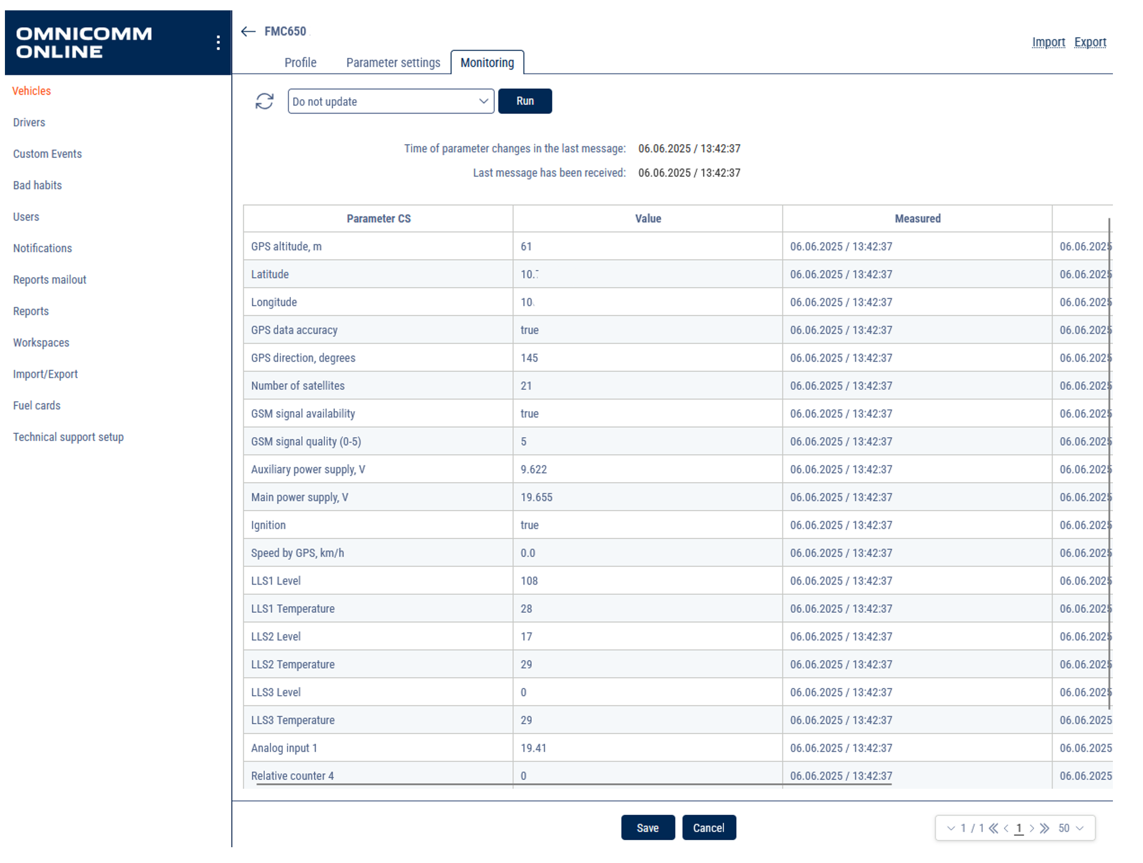
- Open Monitoring tab: check the received values.
Teltonika FMC650
Teltonika FMC650 is a direct successor to current most popular 4G PROFESSIONAL lineup device – FMC640. FMC650 has 4G (LTE Cat 1) network coverage including 2G (GSM) fallback compatibility. Device equipped with GNSS and LTE modules, external GNSS and LTE antennas. Separate GNSS module improves the accuracy of the track, making FMC650 more suitable for free flow electronic tolling system integration. Compared to FMC640 – FMC650 has a new processor that improves the devices computation power along with increased device internal memory it can be tailored to more specific use cases. Switchable CAN terminators that will allow you to use the device in CAN network with numerous nodes. Lastly, it can be powered via USB for easier configuration process. All the features that are supported by FMC640 is also supported by FMC650, therefore it will maximize your fleet efficiency with features like FMS CAN data (J1939), fuel CAN data (J1708), tachograph live data (K-Line), remote tachograph file download, various third party RS232 or RS485 devices support and Dual-SIM or eSIM compatibility. Terminal is suitable for applications like international logistics, refrigerated transport, agriculture, construction & mining, security & emergency services and even more.
FMC650 supports up to 5 digital LLS sensors through RS-485 interface, or single LLS through 232, it has 4 analog inputs, 4 digital inputs and could be used as a refueler in Omnicomm Online.
Install Software
1. Download & install Teltonika Configurator for your OS:
- Unordered List ItemDownload Configurator
2. Install COM Port Drivers for PC communication:
- Unordered List ItemDownload Drivers
Mounting
Fuel Sensor Connection
FMC 650 MOUNTING RECOMMENDATIONS
CONNECTING WIRES
- Wires should be fastened to the other wires or non-moving parts. Try to avoid heat emitting and moving objects near the wires.
- The connections should not be seen very clearly. If factory isolation was removed while connecting wires, it should be applied again.
- If the wires are placed in the exterior or in places where they can be damaged or exposed to heat, humidity, dirt, etc., additional isolation should be applied.
- Wires cannot be connected to the board computers or control units.
CONNECTING POWER SOURCE
- Be sure that after the car computer falls asleep, power is still available on chosen wire. Depending on car, this may happen in 5 to 30 minutes period.
- When module is connected, measure voltage again to make sure it did not decrease.
- It is recommended to connect to the main power cable in the fuse box.
- Use 3A, 125V external fuse.
CONNECTING IGNITION WIRE
- Be sure to check if it is a real ignition wire i. e. power does not disappear after starting the engine.
- Check if this is not an ACC wire (when key is in the first position, most of the vehicle electronics are available).
- Check if power is still available when you turn off any of vehicles devices.
- Ignition is connected to the ignition relay output. As alternative, any other relay, which has power output when ignition is on, may be chosen.
CONNECTING GROUND WIRE
- Ground wire is connected to the vehicle frame or metal parts that are fixed to the frame.
- If the wire is fixed with the bolt, the loop must be connected to the end of the wire.
- For better contact scrub paint from the spot where loop is going to be connected
RS485 Digital Sensors Connection
Connect a single LLS via RS232 port.
Connect FMC650 Tracker
1. Use the USB/2-USB cable or another suitable cable to connect the FMC650 tracker to your PC.* *A cable with an USB/2-USB connector is not included in the FMC650 delivery pack.
2.Open Teltonika Configurator and wait for it to detect the connected device(1- 2 min). The configurator could restart after the recognition tracker.
Configuration
Network Configuration
1. When your device appears, enter the configuration window.
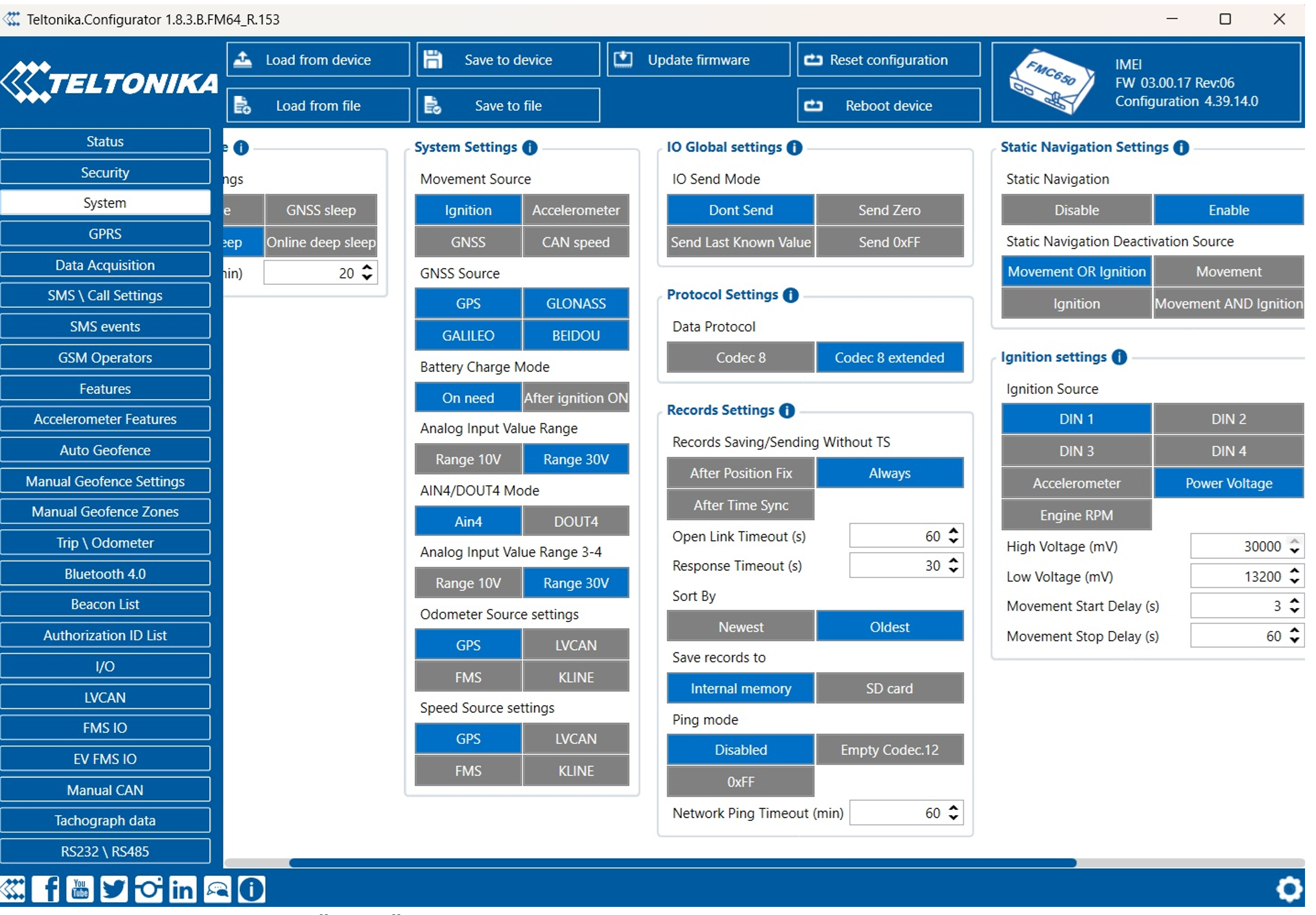
2. Go to the System tab.
Set ignition input:
- The ignition wire must be connected to DIN1 input.
- Under Ignition Source, select the corresponding DIN1 flag.
Under Data Protocol, select one of the following:
- Recommended: Codec 8 or Codec 8 Extended
- Note: Choosing a protocol defines which port you'll configure in the GPRS tab.
Under “Records Settings”.
- Set Sort by: Oldest
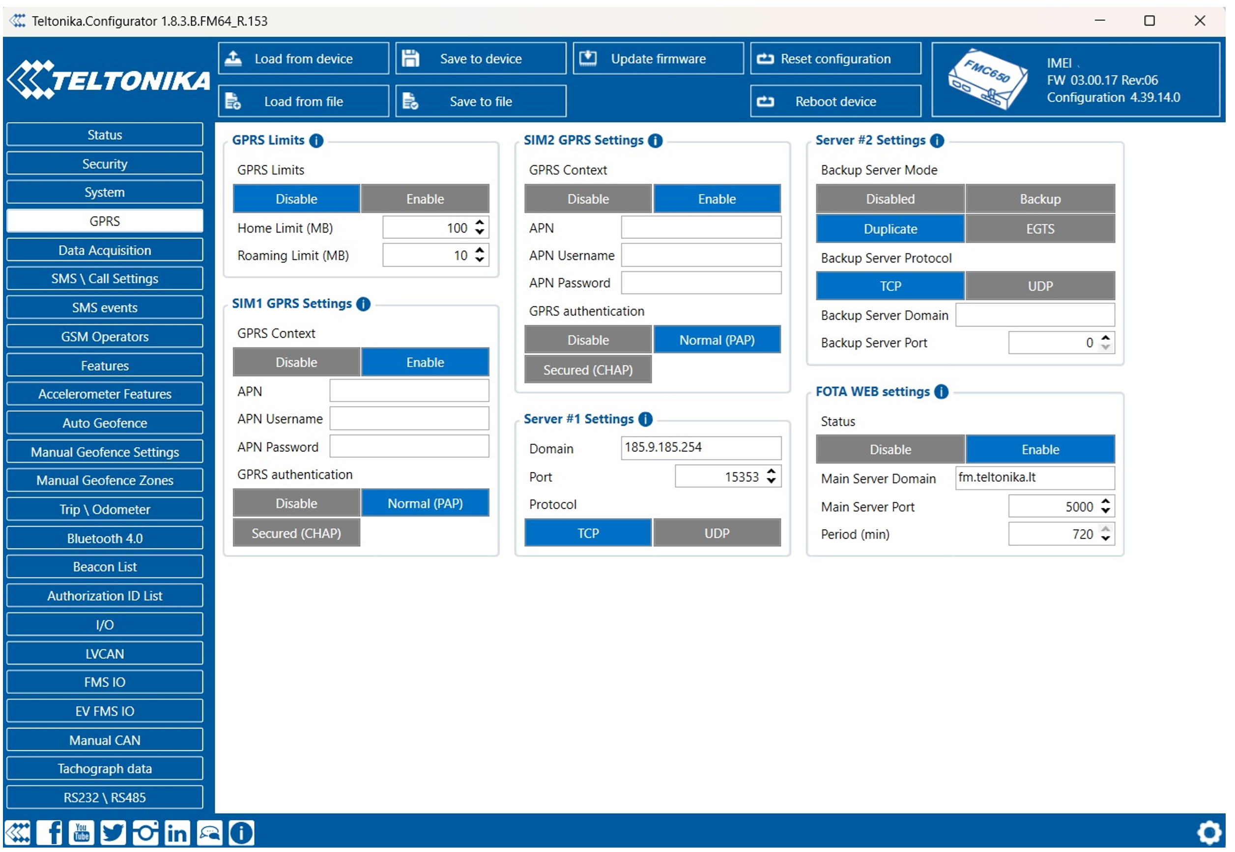
3. Go to the GPRS tab.
Configure APN and password if required by your SIM card provider.
Under Server #1 Settings, enter:
* Domain: 185.9.185.254 or convert.omnicomm.ru * Port:
 Codec 8 Professional: 15352
 Codec 8 Professional Extended: 15353
4.Protocol: TCP.
LLS sensors Settings
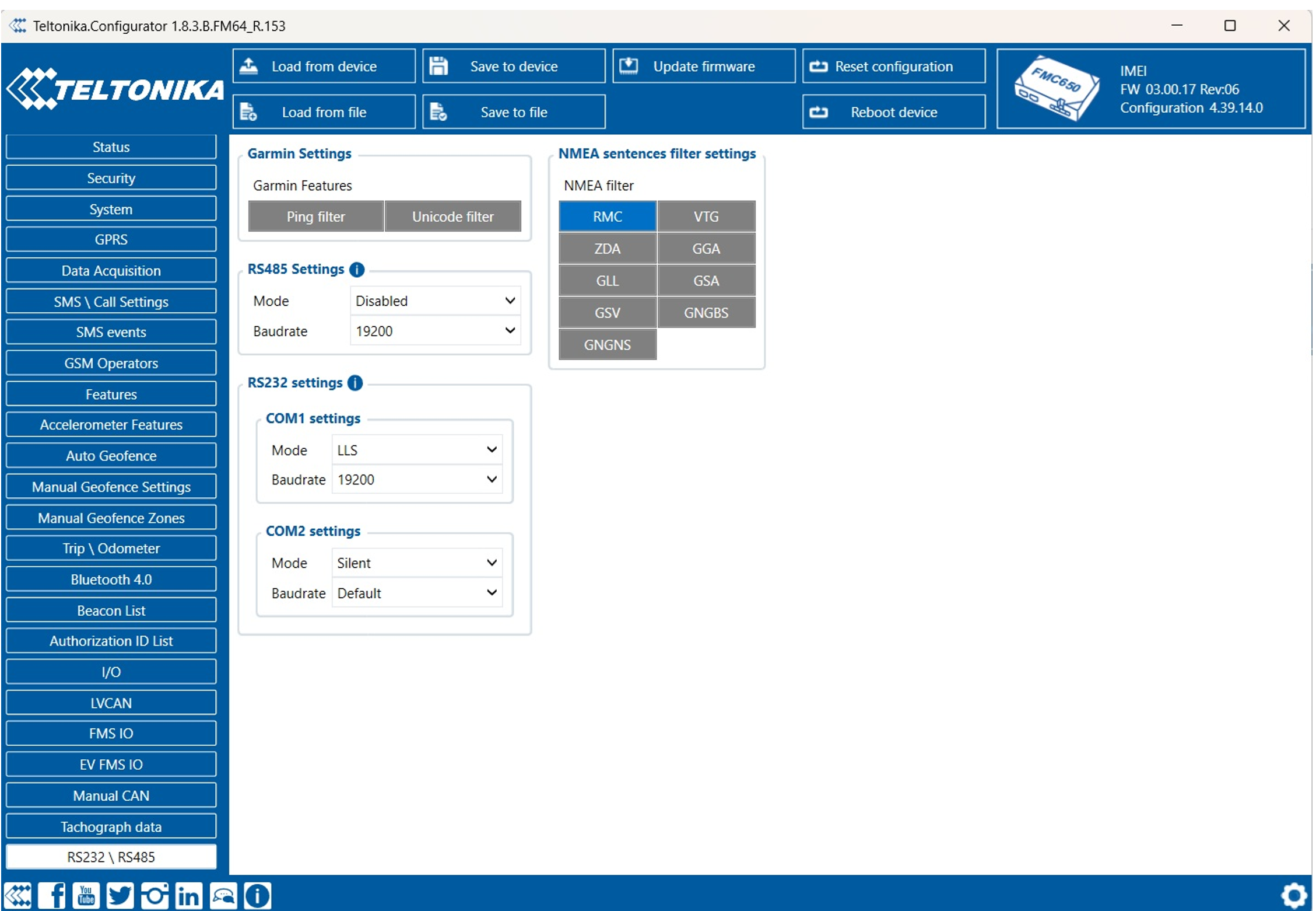
RS485:
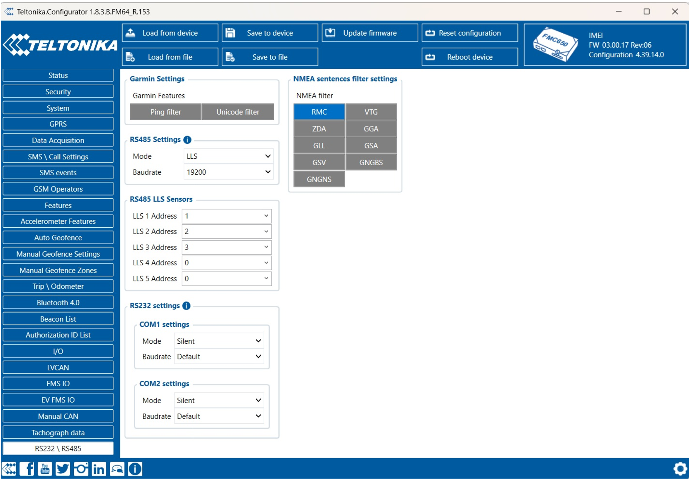
1. Open the RS232/RS485 tab. 2. Under RS485 Settings:
* Mode: LLS * Baudrate: 19200 (must match sensor setting)
3. Under RS485 LLS Sensors:
- Set LLS 1 Address: 1
- Set LLS 2 Address: 2, etc.
- (Sensor IDs must match the ones configured on the LLS sensors.)
RS232:
4. Under RS232 Settings:
- Com 1 or Com 2 Mode: LLS
- Baudrate: 19200
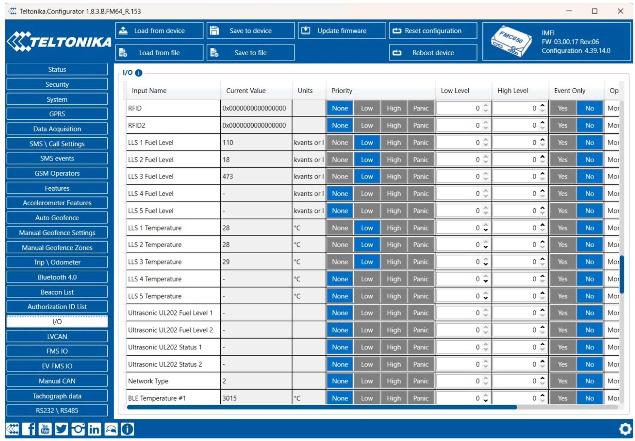
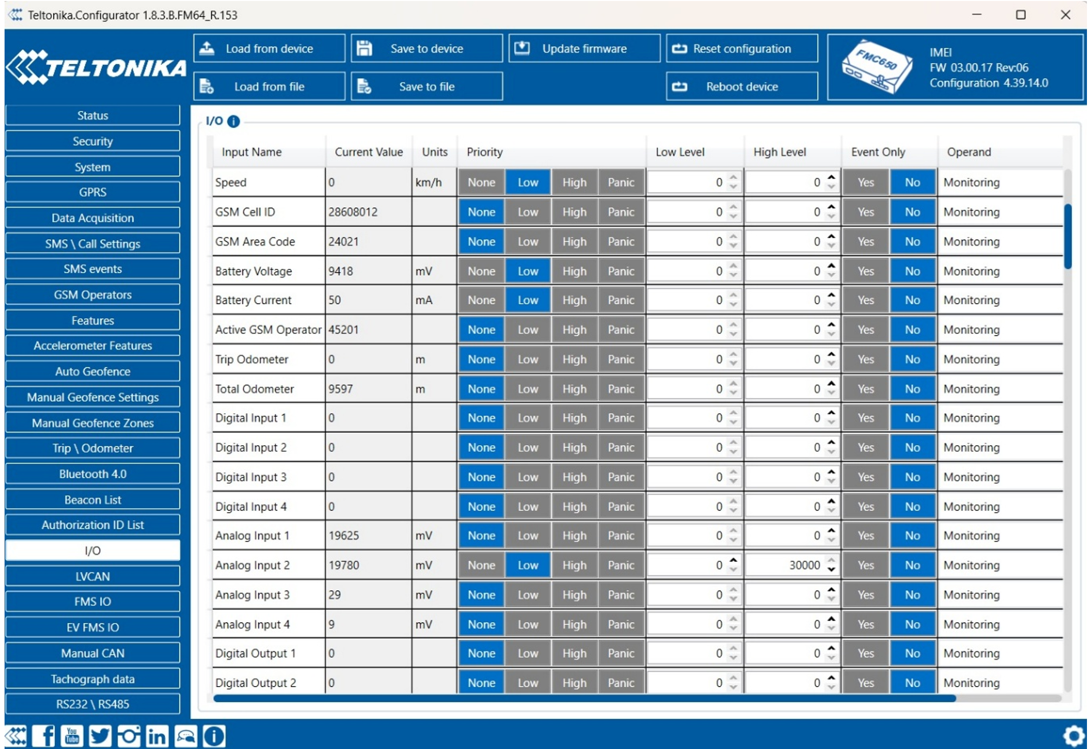
5. Go to the I/O tab.
Set the priority of:
- LLS 1 Fuel Level – LLS 6 Fuel Level (must match sensors number)
- LLS 1 Temperature – LLS 6 Temperature (must match sensors number)
- Set each of these to LOW priority
In case of use Digital or Analog inputs, set the priority and range accordingly.
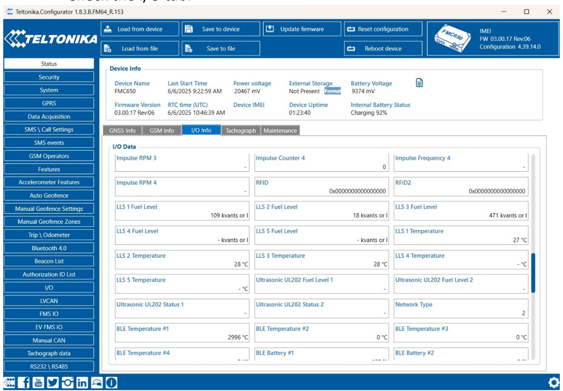
Verify Readings
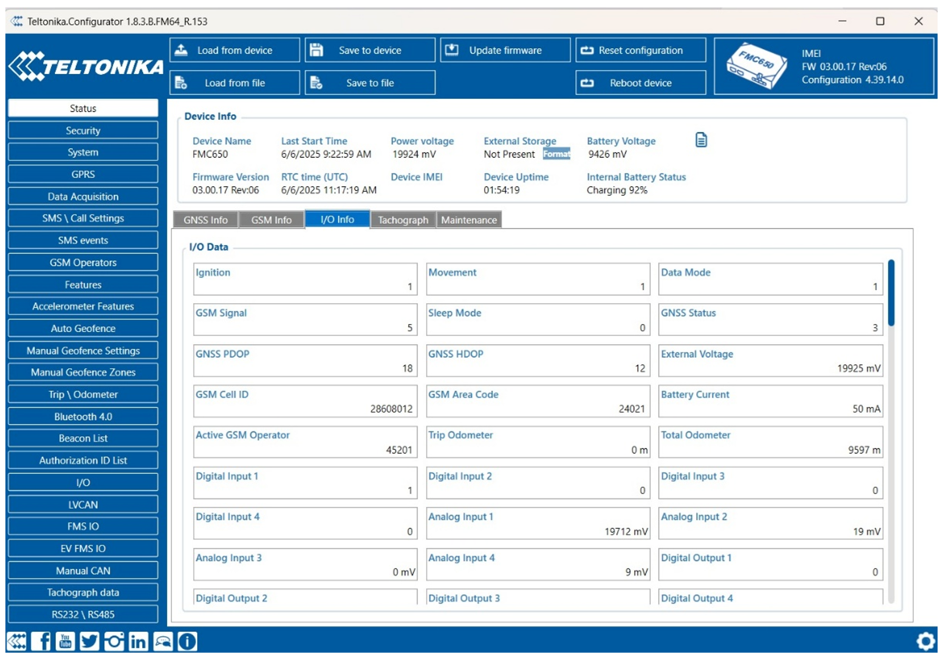
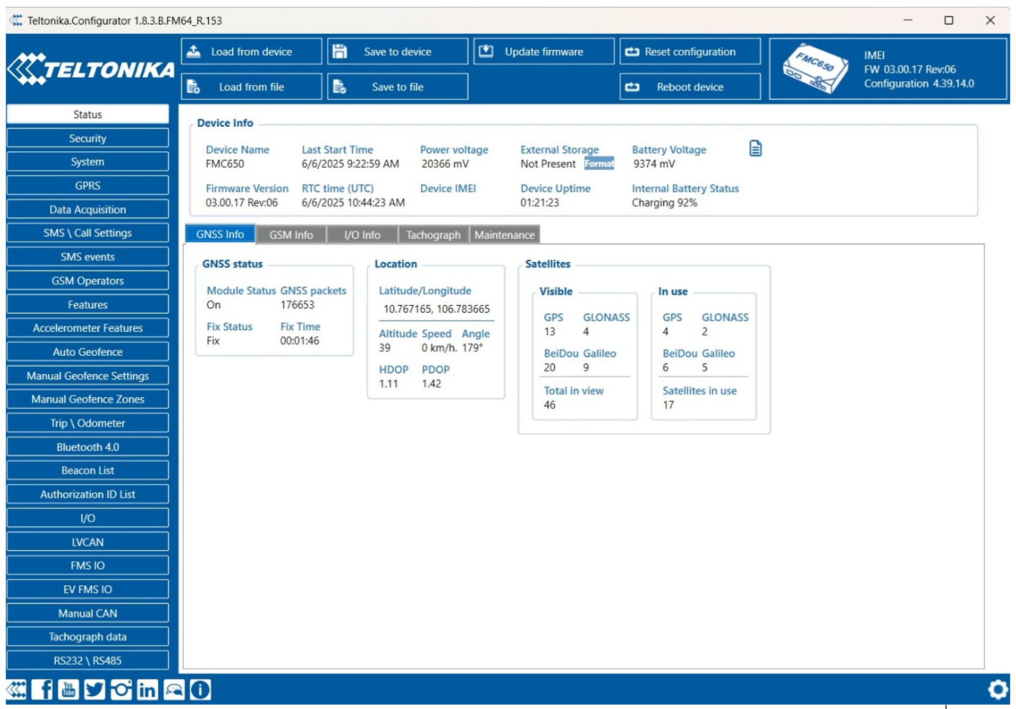
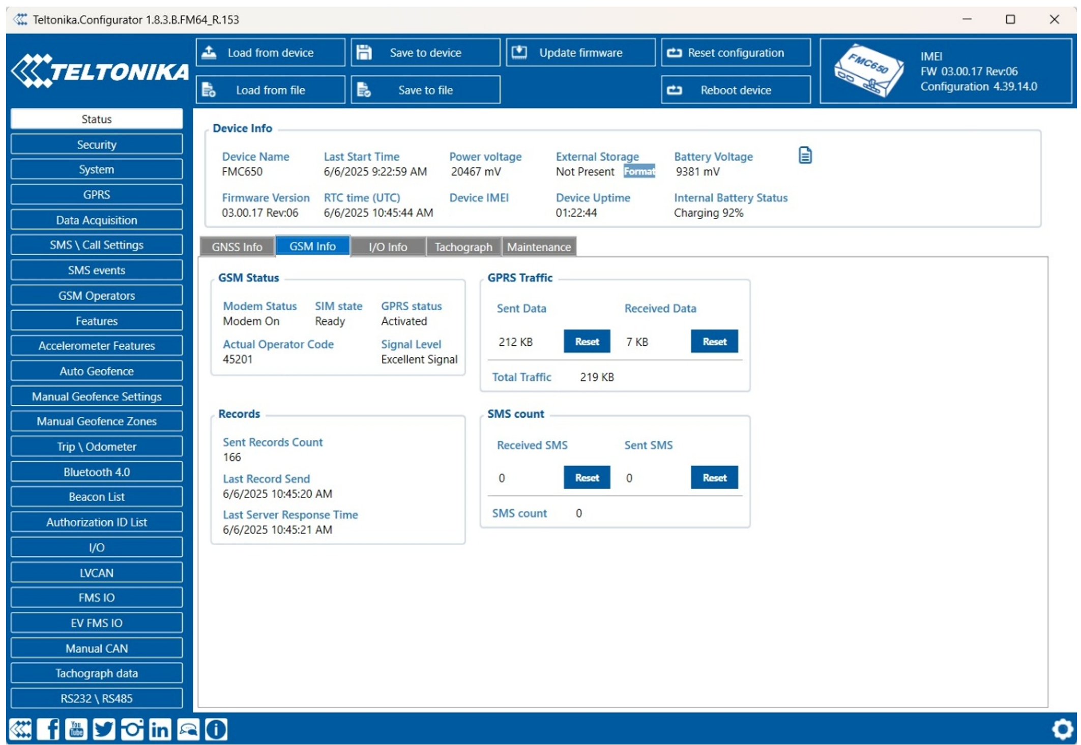
Go to the Status tab to confirm data:
- Check the I/O tab.
- Check GNSS info.
- Check GSM info to verify SIM/network connection and server data transmission:
Add VH and verify Readings on the platform
Profile Setup
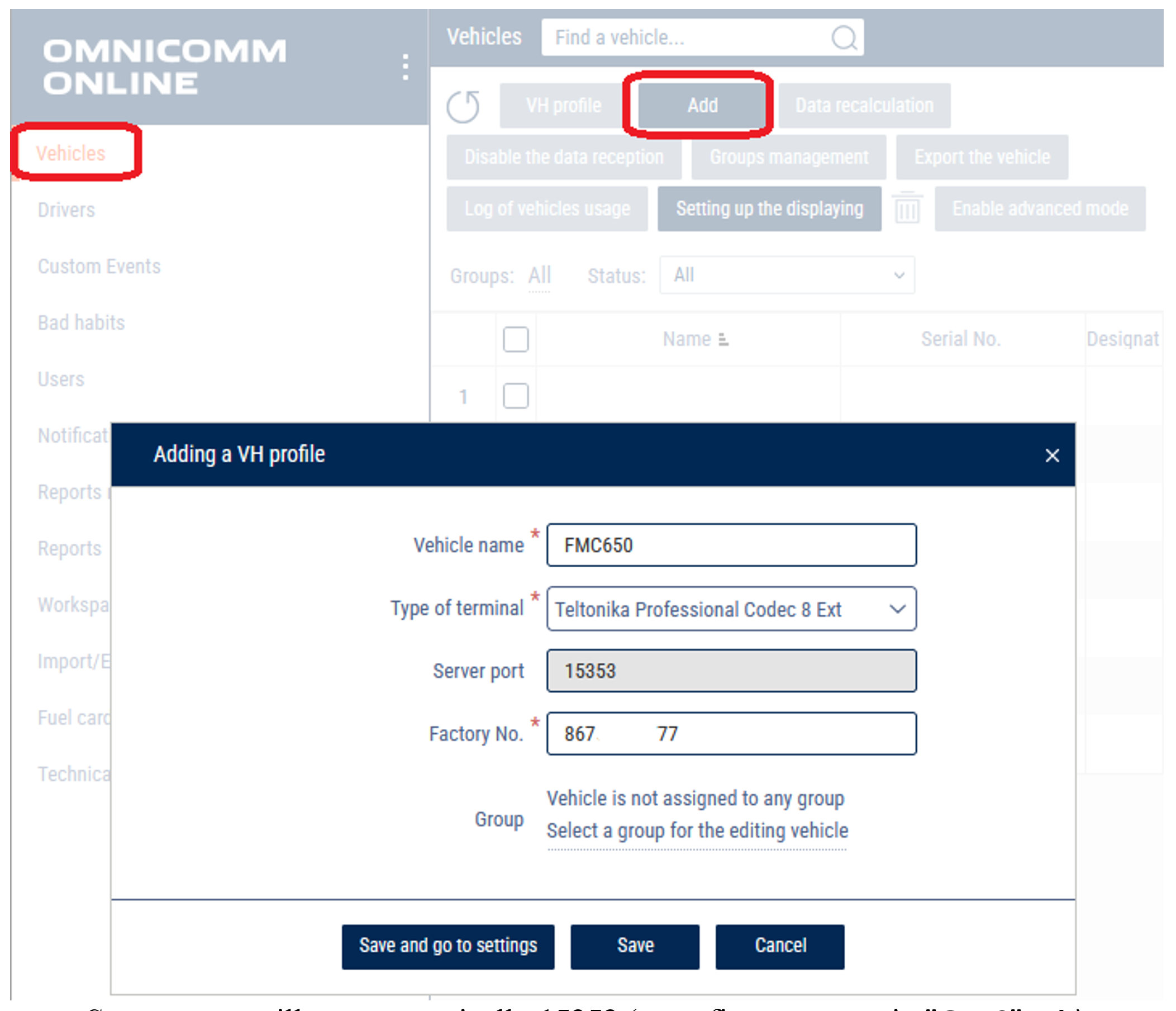
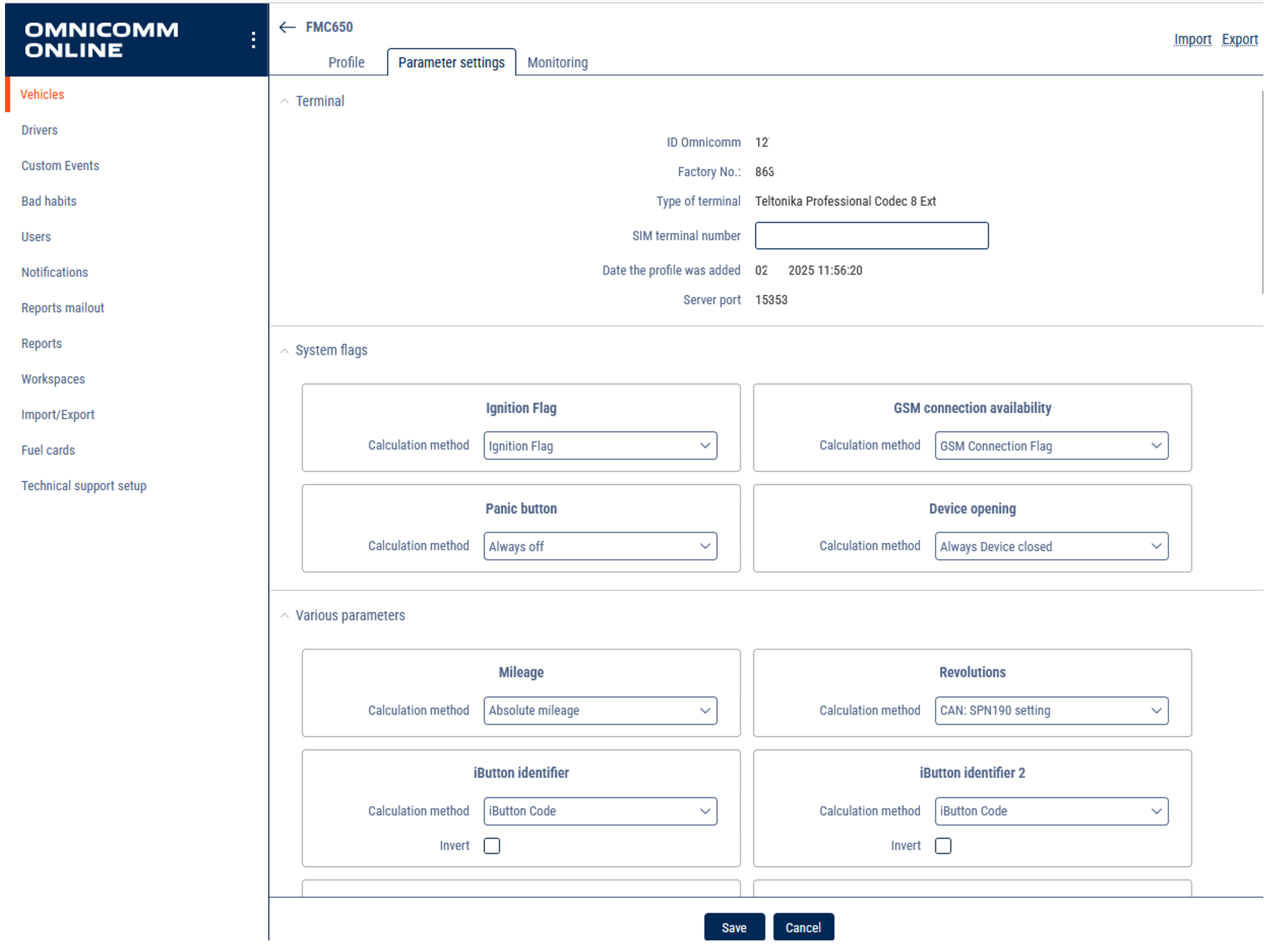
Log in in your account and open Administration-Vehicles tab
- Click Add.
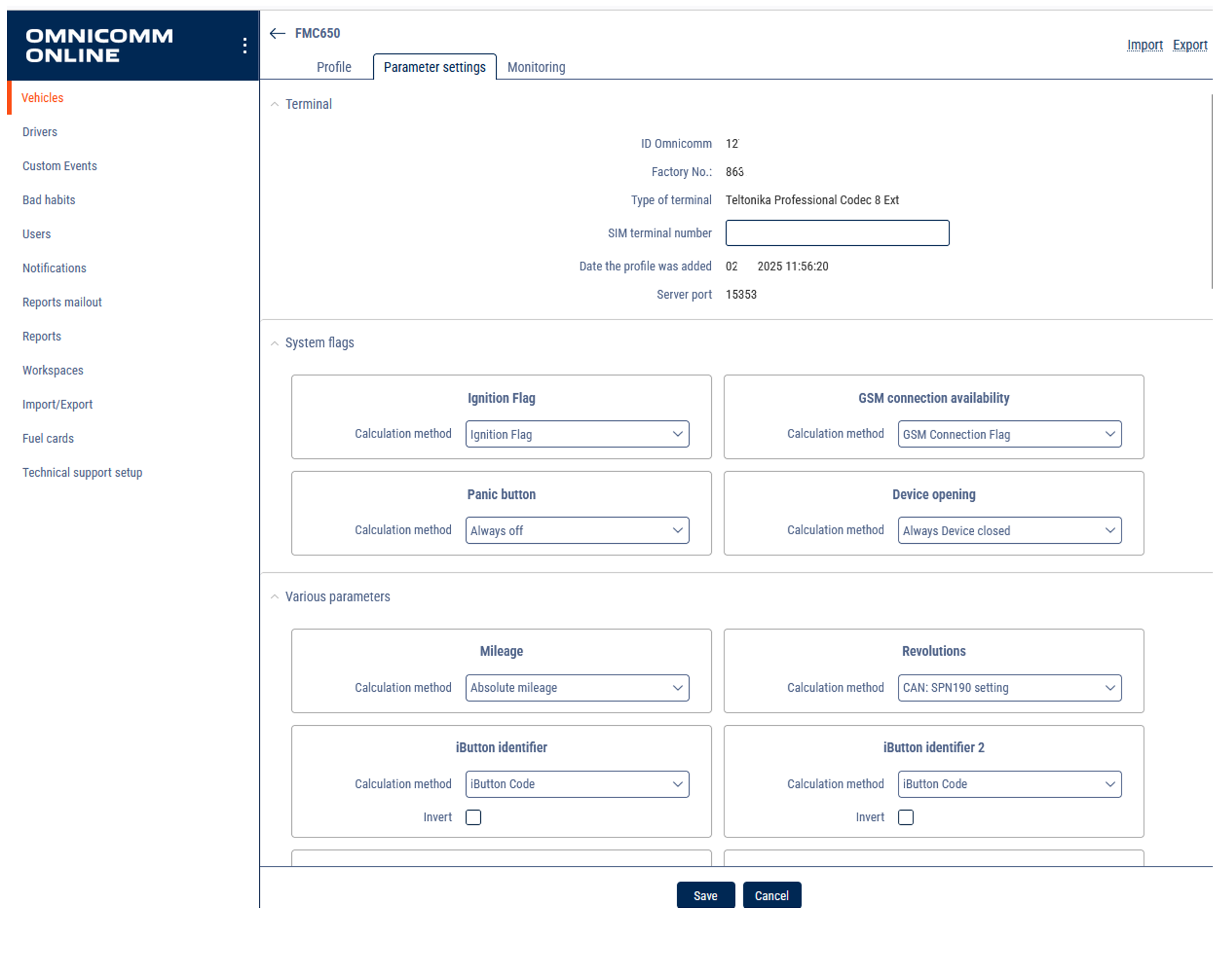
- Choose Type of terminal: Teltonika Professional Codec 8 Ext
- Server port will set automatically 15353 (must fit server port in “GPRS” tab)
- Put your device's IMEI number in Factory No. field
- Put the name in Vehicle Name field (this name will be displayed in reports)
Click on created VH in the list and click VH Profile button
- Open Profile tab set up settings according manual: https://doc.omnicomm.ltd/en/omnicomm_online-administration/vehicle/add/profile_settings
- In the Fuel parameters section, choose a number of tanks and number of installed LLS.
“Fuel tanks” - Select the number of fuel tanks installed on a vehicle:
- Main only means only one fuel tank is installed on a vehicle - Main and additional means two fuel tanks are installed on a vehicle. For refuellers, the main tank is the reservoir, the additional tank is the engine fuel tank. For the vehicle, the main tank is the engine fuel tank, the additional tank is the fuel tank for the optional equipment. - Multitank means up to 6 fuel tanks are installed on a vehicle. Available to users with established rights to objects: Access to Multitank (see Adding and editing a user profile).
Examples:
- Main tank and single sensor: Common scenario. - Main tank and 2 sensors and more: In case of a complicated shape or impossibility to install a sensor in the center, two or more sensors are used for measurement level in a single tank. - Main and additional tank and 2 sensors: A Vehicle has 2 tanks, and each tank is equipped with 1 sensor. - Main and additional tank and 3 or more sensors: A Vehicle has 2 tanks, and each tank is equipped with 1 or more sensors. - Main tank + Multitank or Main and additional tank + Multitank is scenarios for fuel bowser, gas stations e.t.c. For each cistern or isolated compartment could be assigned one or several sensors.
For each tank set up * Parameters of the fuel tank:
- Set up Refueling threshold (recommended value 7% of tank volume, number depends on condition);
- Set up Fuel draining threshold (recommended value 7% of tank volume, number depends on condition);
- Set up Rough filter (depends on road condition);
- Set up Buffer length (depends on road condition);
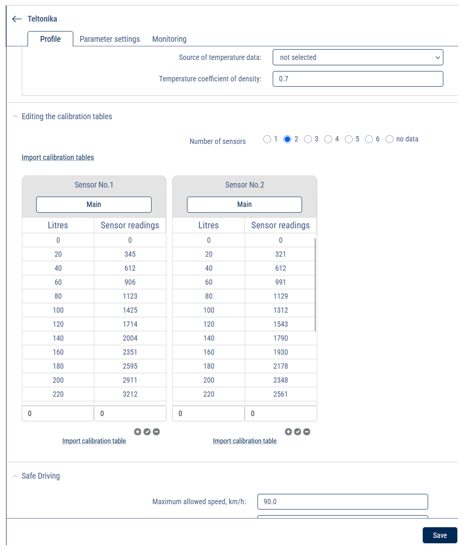
- In Editing the calibration tables, Import calibration tables or fill it manually and link sensors to the tanks.
Open Parameter settings tab:
- Choose and link the necessary parameters.
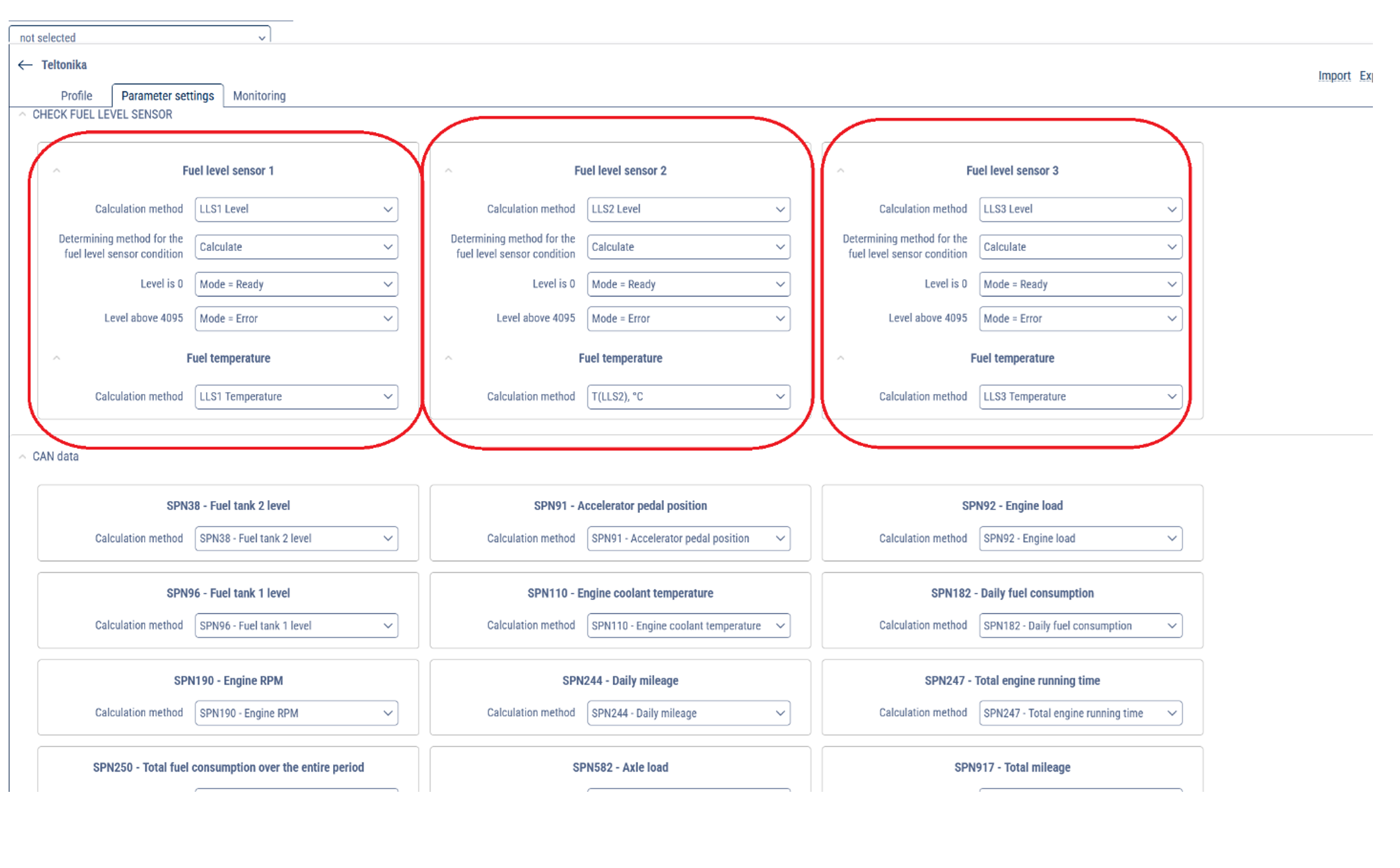
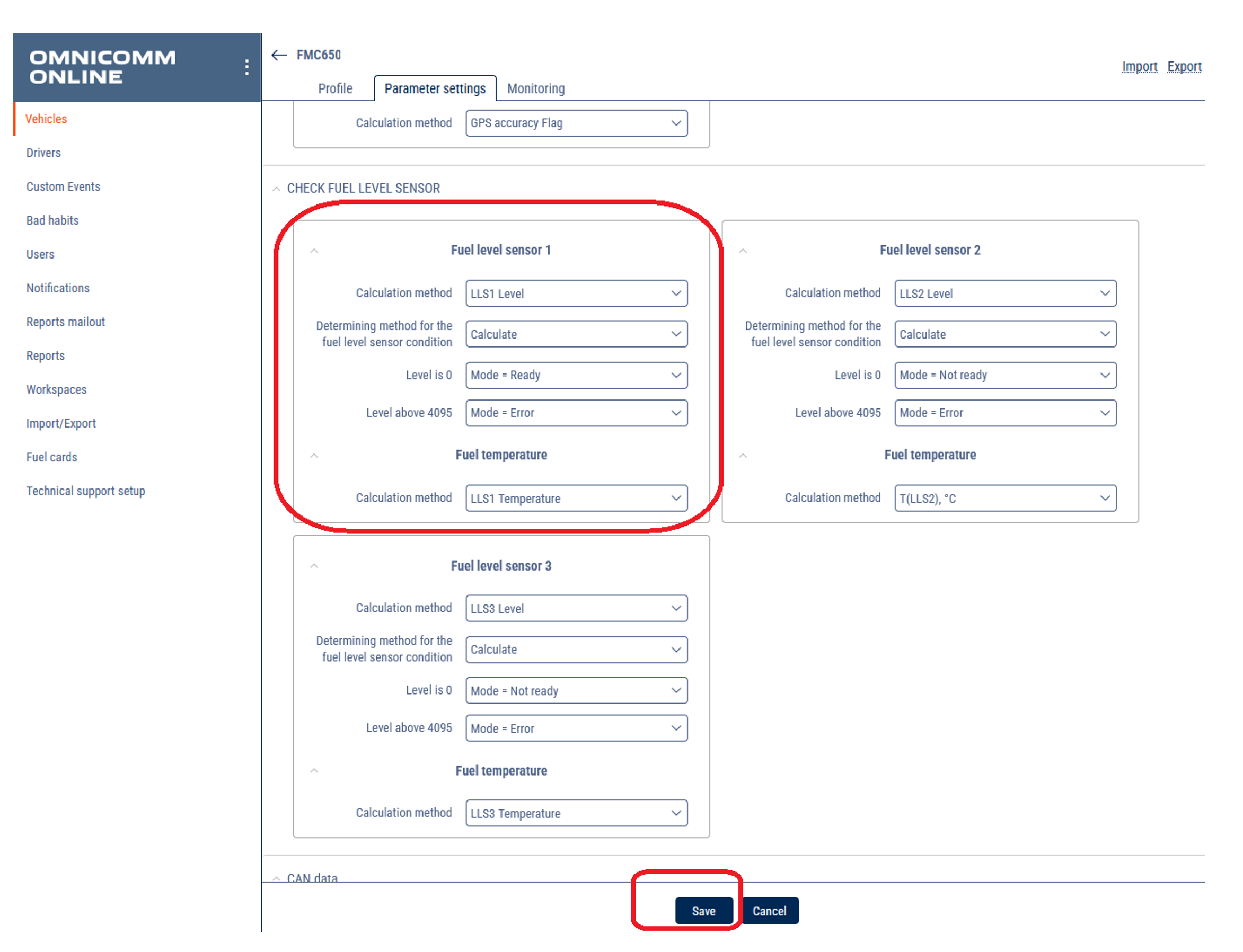
- For CHECK FUEL LEVEL SENSOR choose the source of data for each LLS:
For Fuel level sensor 1:
- Calculation method: LLS1 Level
- Determining method for the fuel level sensor condition: Calculate
- Level is 0: Mode = Ready
- Level above 4095: Mode = Error
- Fuel temperature Calculation method: LLS1 Temperature
For Fuel level sensor 2:
- Calculation method: LLS2 Level
- Determining method for the fuel level sensor condition: Calculate
- Level is 0: Mode = Ready
- Level above 4095: Mode = Error
- Fuel temperature Calculation method: LLS2 Temperature
Same for each sensor.
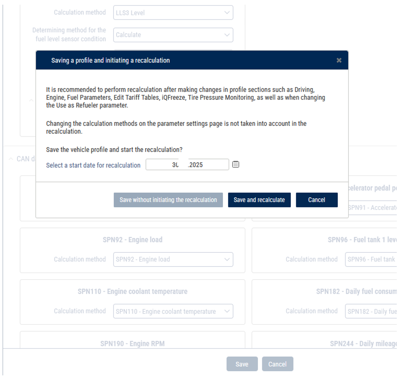
- Click Save and recalculate.
Choose VH in the list and click VH Profile button.
- Open Monitoring tab: check the received values.

