Login
You are currently not logged in! Enter your authentication credentials below to log in. You need to have cookies enabled to log in.
Profile Settings
In the vehicle profile setting in the “Profile” tab, specify the parameter values:
In the “Terminal” section:

“Omnicomm ID” displays the identification number of the terminal installed on a vehicle.
“Factory number” shows the factory number of the terminal, which is set at factory.
“Terminal” shows the terminal model.
“Use as a fuel dispenser” (only for Omnicomm Profi, Teltonika Codec 8 Professional (Ext) terminals) enables/disables the ability to register filling, draining and dispensing of fuel through the fueling gun.
“Type” is the type of vehicle.
“Terminal SIM number” - Enter the phone number of the SIM card installed in the terminal.
“Video terminal ID” - Enter the identification number of Omnicomm OKO Light video terminal installed on a vehicle. Click the “Bind ID” button. ID binding is used to match video files received from Omnicomm OKO Light video terminal with telematics data from the terminal also installed on a vehicle.
In the “Vehicle” section:
“Start date of processing in Omnicomm Online” - date and time of start of data processing by profile in Omnicomm Online.
“Vehicle name” is the name of the vehicle. For example: 10 RU А 123БВ. The vehicle name must be unique for Omnicomm Online. The field “Vehicle name” must not be empty and must not exceed 100 characters.
“Fleet number” is the internal number of a vehicle in an organization.
“Purpose” is the purpose of a vehicle in the organization.
“Brand” is the brand of a vehicle.
“Model” is the model of a vehicle.
“Color” is the color of a vehicle.
“Year of manufacture” is the year of manufacture of a vehicle.
“VIN” is Vehicle Identification Number.
“Engine number” is the engine number of a vehicle.
“Chassis number” - chassis number of a vehicle.
“Vehicle registration plate” shows registration number of a vehicle.
“Manufacturer, model, engine power” - Specify the characteristics of a vehicle engine.
“Vehicle registration certificate” - Enter the number of a vehicle registration certificate.
“Vehicle passport” - Enter a vehicle passport number.
“Lease agreement number” - Enter the agreement number, if a vehicle is leased.
“Vehicle category” - Select the category of a vehicle. Possible options:
• Categories A, B, C, D, D, E, F according to the driving license
• SPEC category - custom vehicles
“Groups”. Click on the Select group hyperlink for a vehicle being edited and select groups from the list to which a vehicle will belong.
In the “Movement” section:

“Mileage and speed calculation method” allows you to select which data and method to use to calculate mileage and speed. Possible options:
• “According to terminal data (without excluding coordinate outliers)” - Omnicomm Online calculates mileage using data received from terminals without excluding drift coordinates.
• “According to terminal data (excluding coordinate outliers)” - Omnicomm Online calculates mileage based on data received from terminals with drift coordinates cut-off
• “Speed by GPS coordinates, mileage by GPS coordinates (excluding coordinate outliers)” - Omnicomm Online calculates mileage by GPS coordinates, cutting off invalid GPS coordinates or coordinates determined by less than 4 satellites.
• “Speed by GPS coordinates, mileage by GPS coordinates (without excluding coordinate outliers)” - Omnicomm Online calculates mileage by GPS coordinates, without cutting off invalid GPS coordinates or coordinates determined by less than 4 satellites.
• “According to speed sensor data” - Omnicomm Online calculates mileage based on the vehicle's regular speed sensor data, taking into account the correction factor (for cars only)
For the standard speed sensor, set the “Speed sensor correction factor” and “Mileage correction factor”, which provide correction of the speed sensor readings.
“Maximum allowable acceleration, m/s²” - Enter the value of the maximum allowable acceleration of a vehicle (lateral, acceleration, braking), above which a sharp change in the nature of a vehicle movement is detected.
“Track parking for more than, min:sec” - Check the box and specify the number of minutes after which a vehicle parking will be registered if the corresponding conditions are met. The conditions for parking/stops detection depend on the parameter “Take ignition into account when determining parking and stops”.
“Track stops for more than, min:sec” - Check the box and specify the number of minutes after which a vehicle stop will be registered if the corresponding conditions are met.
“Take ignition into account when determining parking and stops” - Check the box if it is necessary to register parking and stops taking into account the state of vehicle ignition. The selection is only active when “Track parking for more than, minutes” or “Track stops for more than, minutes” is enabled.
Condition of parking/stops registration taking into account the state of ignition of a vehicle:
• More time has elapsed since the ignition was switched off than specified in the “Track parking for more than, minutes” parameter
• Vehicle speed less than 2 km/h
The condition of parking/stops registration without taking into account the state of ignition of a vehicle:
• Vehicle speed less than 2 km/h for all consecutive events with raw data
• The distance between any events with raw data is less than 800 m
• The time interval between the first and the last event with raw data is greater than the value of the parameter “Track stops for more than, minutes”.
• The time interval between the first and last raw data event does not include periods of data unavailability
“Take into account engine speeds” - Check the box if it is necessary to take into account engine speeds when rendering reports.
“Minimum duration of data unavailability” is the maximum time between the current and the last valid raw data event, after which Omnicomm registers the event of data “unavailability”.
“Drift by mileage” - Specifies thresholds for movement and mileage to cut off drift coordinates while a vehicle is parked with the GPS module running. When a vehicle is moving at a speed of more than 2 km/h, the drift coordinates are not cut off.
The values “Drift by mileage, m” (from 0 to 100 m) and “Drift by mileage, m” (from 0 to 100 m) are adjusted taking into account the average speed of a vehicle. The default value for both parameters is 20 m.
In the “Engine” section:

“Correction factor for RPM meter” is the factor for converting the number of pulses from the RPM meter to the number of revolutions.
“Engine RPM limit” is the engine RPM value, when exceeded, Omnicomm Online registers a vehicle operation under the load limit. The default value is 5,500 rpm.
“Engine idle RPM level” is the engine RPM value, when exceeded, Omnicomm Online registers vehicle movement. The default value is 1,000 rpm.
In the “Fuel parameters” section:
“Fuel tanks” - Select the number of fuel tanks installed on a vehicle:
• “Main only” means only one fuel tank is installed on a vehicle
• “Main and additional” means two fuel tanks are installed on a vehicle. For refuellers, the main tank is the reservoir, the additional tank is the engine fuel tank. For the vehicle, the main tank is the engine fuel tank, the additional tank is the fuel tank for the optional equipment.
• “Multitank” means up to 6 fuel tanks are installed on a vehicle. Available to users with established rights to objects: Access to Multitank (see Adding and editing a user profile).
Parameters of the main fuel tank

The units of fuel parameters liters or gallons are specified depending on the server settings.
“LLS5”:

“Monitor fuel quality LLS 5” - Check the box to monitor fuel quality using Omnicomm LLS 5 level sensors.
“Autotuning coefficient change threshold, %“ - Specify the allowable value of autotuning coefficient change, if exceeded, the “Correction coefficient change threshold exceeded” event will be registered. The default value is 7. Possible values: 0 to 100.
“Autotuning factor stabilization interval, seconds” - 0 (unchangeable value).
“Fuel”:
“Parameters of the main fuel tank” for the vehicle and the additional tank for the fuel dispenser:
“Refueling threshold, l” (from 0 to 28,000) is the volume of fuel by which the total volume of fuel of a vehicle must be increased in order for fuel refueling to be registered. The default value of the refueling threshold is 7% of the tank volume.
“Drainage threshold, l” (from 0 to 28,000) is the volume of fuel by which the total volume of fuel of a vehicle must be reduced in order for the fuel drainage to be registered. The default value of the drain threshold is 7% of the tank volume.
“Average consumption per 100 km, l” (from 0 to 1,000 with accuracy to 0.1 l) is the volume of fuel consumed by a vehicle per 100 km (only for cars).
“Average consumption per engine hour, l” (from 0 to 1,000 with accuracy up to 0.1 l) is volume of fuel consumed by a vehicle for an hour of engine operation (only for cars).
“Average fuel consumption for data collection period, l” (from 0 to 1,000 with accuracy up to 0.1 l) is the volume of fuel consumed by a vehicle during the time between taking readings from the sensor (only for cars).
“Correction factor for fuel sensors” (from 0.01 to 1.99) is used to correct readings of Omnicomm LLS fuel level sensors.
“Fuel type” - Select the type of fuel to calculate the amount of CO2 emissions. Possible options: gasoline, diesel and not specified.
“Parameters of fuel data processing algorithms”:

“Rough filter” is the number of fuel level measurements before and after refueling/draining that are used in the refueling/draining search algorithm to filter out fuel level fluctuations. Rough filter size (5 - 50), the default value is 15.
The fill/drain thresholds and rough filter size are selected based on the tank volume, the amount of fill/drain detected and the vehicle operating conditions.
In cases where operating conditions and vehicle characteristics cause large fluctuations in fuel level, it is recommended to increase the values of refueling/drain thresholds and rough filter value relative to default values.
“Buffer length” - Specify the buffer length for the fuel data smoothing algorithm. Buffer length size (10 - 100), the default value is 35.
“Additional parameters for the algorithm to search for refills and drains”:

For the algorithm for searching for refueling and draining “Take time parameters into account”:
“Maximum allowable refueling interruption time, sec” is the time interval in the process of refueling during which the fuel level may not rise. The default value is 30 s.
“Maximum allowable draining interruption time, sec” is the time interval in the process of draining, during which the fuel level may not drop (taking into account average fuel consumption). The default value is 30 s.
The setting of time parameter values should be done by considering the “Data collection period” value and analyzing specific areas where no drain/fill events were detected.
Quartile is the arithmetic mean of some number of points with fuel raw data before the start or after the end of fuel operation with a quarter of minimum and maximum values screened out and is used to determine the fuel level before and after refueling/draining.
The quartile is calculated by the number of fuel level values obtained during the time specified in the “Time interval for quartile calculation, min” parameter.
“Time of fuel operation start in motion, sec” is the allowable time of fuel operation start in motion.
“Time of fuel operation end in motion, sec” is selected depending on the filtering value set in the terminal. Recommended values for filtration levels:
• Disabled - 0.
• Weak - 60.
• Average - 120.
• Strong - 200.
• Maximum - 300.
“Allowable deviation from the movement section boundary, sec” is the time during which the fuel level is current at the start or end of movement.
“Maximum allowed speed for filtering at speed, km/h” - Specify the speed (with filtering enabled) above which fuel operations will not be displayed in reports.
“Fuel weight calculation”:
“Method of mass calculation” - Select the method of fuel mass calculation. Possible options:
• by level, temperature and standard density
• by level and actual density
For the “by level, temperature and standard density” method:

“Fuel average density at 20°C, kg/m3” - Enter the fuel standard density. The default value is 860.0 kg/m3.
“Temperature data source” - Select the universal input to which the temperature sensor is connected.
“Temperature density factor” - Enter the temperature density factor. The default value is 0.7.
For the “by level and actual density” method:

“Density data source” - Select the universal input to which the density sensor is connected.
Multitank parameters
• Select Multitank
• Specify the number of tanks

Tank parameters
Specify the following parameters for each tank:
“Tank type” - Select the tank type. Possible variants: consumption tank, non-consumption tank without output counter.
“Name” - Enter the name of the tank.
For consumption and non-consumption tanks, specify the fuel parameters in the same way as for the main tank.
Editing calibration tables

Select the number of fuel level sensors installed on a vehicle.
When loading multiple tables from a file, specify the network addresses of the fuel level sensors.
For each fuel level sensor, select the tank (“Main” or “Additional”) in which the fuel level sensor is installed.
In case of Multitank, select the tank in which the sensor is installed by clicking Unlinked.
Highlight with the cursor the row whose values you want to change. In the input cells below the table, enter new values for this row of the table. To enter row values into the table, press ![]() .
.
To add/remove a table row, press ![]() .
.
In the “Universal input settings” section:
Analog universal input
“Universal input type” displays the “analog” input type, set during terminal setup.

“Name of the equipment on the universal input” - Enter the name of the sensor or the name of the measured value.
“Universal input correction factor”. The default value is 1.
“Take into account the switching state of additional equipment on the universal input” registers the switching on of additional equipment at the universal input.
“Threshold value of switching on the universal input” - For analog sensors it is recommended to set the value beyond the sensor measurement range, which will help to avoid registration of unnecessary sensor switching off events. When the “Take into account the switching state of additional equipment on the universal input” is turned off, the field “Threshold value of switching on the universal input” is not editable.
“Take into account exceeding the allowable value at the universal input” registers exceeding of the allowable value at the universal input.
“Threshold of maximum allowable value on universal input” - Enter the measured value, when exceeded, Omnicomm will register operation with exceeded allowable value. If “Take into account exceeding the allowable value at the universal input” is turned off, the field “Threshold of the maximum allowable value at the universal input” is not available for editing.
To save all changes, click the “Save” button.
Potential universal input
“Universal input type” displays the “potential” input type, set during terminal setup.

“Name of the equipment on universal input” - Enter the name of the sensor or the name of the measured value.
Pulse universal input
“Universal input type” displays the “pulse” input type, set during terminal setup.

“Name of the equipment on universal input” - Enter the name of the sensor or the name of the measured value.
“Universal input correction factor” is recommended to be changed only if the input calibration has been incorrectly performed.
“Take into account the switching state of additional equipment on the universal input” registers the switching on of additional equipment at the universal input.
When the “Take into account the switching state of additional equipment on the universal input” is turned off, the field “Threshold value of switching on the universal input” is not editable.
“Take into account exceeding the allowable value at the universal input” registers exceeding of the allowable value at the universal input.
“Threshold of maximum allowable value on the universal input” - Enter measured value, when exceeded, Omnicomm will register the operation with exceeding the allowable value. If “Take into account exceeding the allowable value at the universal input” is turned off, the field “Threshold of the maximum allowable value at the universal input” is not available for editing.
In the section “Setting initial values for maintenance control”:

“Mileage record” allows you to select the data source to record a vehicle mileage for control over maintenance. Possible options:
• “Ignore mileage” - Mileage calculation for maintenance control will not be performed
• “Use odometer” - The calculation is based on the odometer readings set in the vehicle profile in the “Mileage and speed calculation method” parameter. Possible options: from terminal (with drift), from terminal (without drift), speed by GPS, mileage by GPS coordinates, from speed sensor

“Initial odometer value, km” - Enter the odometer reading mileage value.
“Date and time of odometer initial reading” - Enter the date and time when the odometer reading was taken.
“Current odometer value, km” displays the mileage value calculated by Omnicomm using the odometer. To display the current odometer value at the first installation or adjustment, you must save the changes to the vehicle profile and then reopen the vehicle profile.
• “Use CAN-bus odometer value” - The mileage calculation for maintenance control will be performed according to the values received from the CAN-bus

“Current odometer value, km” displays the last mileage value sent by the terminal based on the CAN-bus odometer readings.
“Engine hours record” allows selecting the source of data to record vehicle’s engine hours for control over maintenance. Possible options:
• “Do not count engine hours” - Engine hours will not be counted for the purpose of maintenance control
• “Use engine hour meter” - the calculation of engine hours will be based on the readings of a vehicle's engine hour meter and engine running time.

“Coefficient for conversion of engine operation time into engine hours” - Specify the coefficient for conversion of engine operation time into engine hours specified in a vehicle passport.
“Initial counter value, eh” is the value of the engine hour meter.
“Date and time when the initial odometer reading was taken” - Enter the date and time when the engine hour meter reading was taken.
• “Use CAN-bus hours value” - The calculation of the engine hours for the maintenance check will be performed using the values received from the CAN-bus.

“Current hour meter value, eh” - the number of hours received from the CAN-bus.
In the “Assigning a driver to a vehicle” section:

“Driver registration by applying a tag” - Check the checkbox to register the driver by applying an RFID card or iButton key.
The assignment of a driver to a vehicle is automatically terminated when this driver is assigned to another vehicle or when another driver is assigned to the same very vehicle.
“End registration with ignition off” - Check the box to end registration when ignition off is detected.
“End registration by removing the tag from its holder” - check the checkbox to end enrollment when it is detected that the iButton key or RFID card is removed from the holder.
“Restore registration if tag is re-applied within specific time” - Specify the time within which the RFID card or iButton key must be re-applied to automatically restore driver registration. The field is active only if the “End registration by turning off the ignition” or “End registration by removing the tag from its holder” parameter is enabled.
In the “Setting temperature sensors” section:

“No.” shows the serial number of the temperature sensor.
“Name” - Enter the name of the temperature sensor. For example, a cabin. The maximum number of characters is 16.
In the “Tire pressure monitoring” section:

“Generate events from TPMS” - Check the checkbox to process data from the tire pressure monitoring system.
“Allowable duration of data unavailability, minutes” - Enter the value after which the “No data from tire pressure monitoring system” event will be registered in case of no data. Possible values: 0 to 1140 min. The default value is 15.
“Number of vehicle axles” - Select the number of vehicle axles. Possible values: 1 to 13.
When using TPMS Conti Pressure Check tire pressure monitoring system, the axles and wheels must match the TPMS Conti Pressure Check configuration:


The wheel position data in TPMS Conti Pressure Check is transmitted in CAN J1939 format. The wheels are numbered from left to right from the first (top) axle, so that the first wheel is located on the driver's side.
“Correct tire pressure, kPa” - Enter the tire pressure value set by a vehicle manufacturer. Possible values: 0 to 1,000 kPa.
“Allowable deviation of tire pressure, kPa” - Enter the value of allowable deviation from normal tire pressure, above which the “Tire pressure drop” event is registered.
“Maximum allowable tire temperature, °С” - Enter the value of tire temperature, if exceeded, the “Tire temperature rise” event is registered. Possible values: -125 to 125 °C. The default value is plus 60 °C.
To copy axle, wheel and tolerance settings from another vehicle, click the Copy from another vehicle link.
In the “iQFreeze” section:

“Process data from iQFreeze” - Check the box to control data from iQFreeze.
“Allowable duration of data unavailability, minutes”. Possible values: 0 to 1,440 min. The default value is 15 min
“Allowable upward deviation of the CHU temperature from the set temperature”. Possible values: 0.00 to 100.00 °C
“Allowable downward deviation of the CHU temperature from the set temperature”. Possible values: 0.00 to 100.00 °C
In the “CAN threshold values” section:

Add the required CAN parameters and specify the values which are as follows:
“Correction factor” - Enter the value of the correction factor.
“Switching threshold” - Enter measured value, when it reaches which Omnicomm will register switching on.
“Lower threshold of nominal values” - Enter the measured value, above which Omnicomm will register operation at nominal values.
“Upper threshold of nominal values” - Enter measured value, when exceeded, Omnicomm registers operation with exceeding the nominal value.
Multitank vehicle profile editing
In the program window, select from the list the vehicle profile you would like to edit. Click “Multitank vehicle profile”. A window will open:

In the “Terminal” section:

“Terminal” – the terminal's model.
“ID” the identification number of the Terminal installed on the vehicle.
“Factory number” the factory number of the Terminal, which is assigned during the production.
“Phone number” enter the phone number of the SIM card in the Terminal.
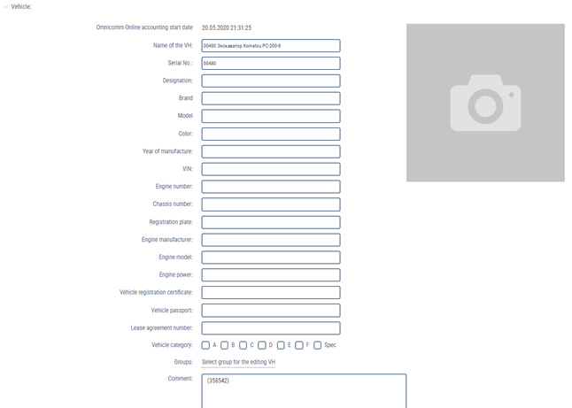
In the “Vehicle” section:

“Profile added date” - the date and time when the profile was added to Omnicomm Online.
“OO account creation date” - date and time when the profile data was first processed in Omnicomm Online.
“Current profile version start date” - the date and time when the vehicle profile was last modified.
“Vehicle Name” – the state registration number (plates) or the name of the vehicle. Example: 10 RU А 123BV. The vehicle name must be unique in Omnicomm Online. The “Vehicle Name” field must not be empty and must not exceed 100 characters.
“Depot ID” – the internal number of the vehicle within the organization.
“Designation” – the vehicle's designation within the organization.
“Brand” – the vehicle's brand.
“Vehicle category” - select the category of the vehicle. Possible options:
- Categories A, B, C, D, E, F, according to the traffic regulations of the Russian Federation
- Category SPEC - specialized machinery
“Special equipment model” - select the model of equipment or vehicle for which you wish to display additional operating parameters in the Log report. Possible options:
- TG series grader - operation parameters apply to these vehicle models only, the connection is performed via CAN J1939
- Excavator WX200, TX200 - operation parameters apply to these vehicle models only, the connection is performed via CAN J1939
- Tractor PTZ K4, K7 - operation parameters apply to these vehicle models only, the connection is performed via CAN J1939
- Axle load (VOLVO) - parameters apply only to VOLVO trucks with a CAN bus error, which transmit the wheel number instead of the axle number, the connection is performed via CAN J1939
- Axle load (ALM) – the ALM axle load detection system is connected via the RS-232 interface
- Logset Harvester – parameters apply to this vehicle model only, the connection is performed via the CAN bus
- J1939 axle group load - parameters for European trucks/buses, the connection is performed via the CAN bus
- J1939 fuel parameters – parameters for European trucks/buses, the connection is performed via the CAN bus, instantaneous fuel consumption is displayed
- CanExtender – parameters for the CANExtender equipment (UI extender) connected via the CAN bus
To display additional vehicle operation parameters, check the box “Technical parameters operation displaying” in the Log report settings (see Omnicomm Online. User Manual. Log report).
We are constantly expanding the list of special equipment models. If you cannot find the description you are looking for, please contact the Omnicomm technical support team ([email protected]).
“Groups”. Click on the Select group for the vehicle hyperlink and select from the list the groups to which the vehicle will belong to.
In the “Driver sign in on a vehicle” section:

“Driver sign in by tag reading” – у- check the box to sign in a driver when an RFID card or an iButton key is scanned.
The driver is automatically signed out on the vehicle when the current driver signs in on another vehicle or when another driver signs in on this vehicle.
“Sign out when the ignition is turned off” – check the box to sign the driver out when the ignition is turned off.
“Sign out when the tag is removed from the holder” – check the box to sign the driver out when the iButton key or the RFID card are removed from the holder.
“Resume sign in if the tag is reinserted within” – specify the time in which the RFID card or the iButton key must be reinserted to automatically resume driver sign in. The field is active only when the “Sign out when the ignition is turned off” or “Sign out when the tag is removed from the holder” parameters are enabled.
In the “Tire Pressure Monitoring” section:

“Create events from TPMS” – check the box to process data from the tire pressure monitoring system.
“Allowed duration of data absence, minutes” – enter the time after which, in the absence of data, the “No data from the tire pressure monitoring system” event will be recorded. Possible values: from 0 to 1140 min. Default value – 15.
“Number of axles” – select the number of vehicle axles. Possible values: from 1 to 13.
“Normal tire pressure, kPa” – enter the tire pressure value set by the vehicle's manufacturer. Possible values: from 0 to 1000 kPa.
“Permissible tire pressure deviation, kPa” – enter the value of the permissible deviation from the normal tire pressure. If this value is exceeded, the “Drop in tire pressure” event will be recorded.
“Maximum permissible air temperature in the tire, °C” – if this value of air temperature in the tire is exceeded, the “Raise of tire temperature” event will be recorded. Possible values: from -125 to 125 °C. Default value: 60 °C.
To copy the settings for axles, wheels, and permissible values from another vehicle, click the Copy from another vehicle link.
In the “Engine” section:

“Correction coefficient for the RPM sensor” – the coefficient of conversion of the number of pulses recorded by the RPM sensor into the number of revolutions.
“Limit level of engine RPM” – the value of engine revolutions, above which Omnicomm Online will record vehicle operation under maximum (ultimate) load. Default value - 5500 RPM.
“Engine idle RPM” – is the value of engine revolutions, above which Omnicomm Online will record the movement of the vehicle. Default value - 1000 RPM.
In the “Safe driving” section:

“Maximum allowed speed, km/h” – the value of the vehicle speed, above which Omnicomm will register vehicle movement as exceeding the maximum allowed speed. Possible values: from 0 to 300 km/h. Default value - 0 km/h (no violations will be recorded).
“Speed limit, km/h” – the value of the vehicle speed, above which Omnicomm will register vehicle movement as exceeding the speed limit. Possible values: from 0 to 300 km/h. Default value - 120 km/h.
The value of the "Speed limit, km/h" parameter must be greater than the value of "Maximum allowed speed, km/h"
“Sensitivity, km/h” – enter the permissible amount of speed value variation. If the maximum allowed speed or the speed limit are exceeded by a value lesser than this, no violation will be recorded. Possible values: from 0 to 99 km/h. Default value - 2 km/h.
“Allowed turning speed, km/h” – the value of vehicle speed while turning. If this value is exceeded, Omnicomm will record vehicle movement with an exceeded turning speed. Possible values: from 0 to 300 km/h. Default value - 30 km/h.
“Speed limit while turning, km/h” – the value of the vehicle speed, above which Omnicomm will register vehicle movement as exceeding the speed limit while turning. Possible values: from 0 to 300 km/h. Default value - 50 km/h.
“Minimum duration of exceeding the vertical acceleration threshold” – when the vertical acceleration threshold is exceeded for longer than indicated, the corresponding event will be recorded. Possible values: from 0 to 60039 sec. Default value - 0 (no violations will be recorded).
“Maximum duration of idle run at engine operating temperature” – enter the amount of time after which, during idle engine run at operating temperature, the corresponding event will be recorded. Possible values: from 0 to 60039 sec. Default value - 0 (no violations will be recorded).
“Engine operating temperature” – specify the range of temperature in which the engine can operate regularly. Possible values: from 0 to 300 °C. Default value: 80 and 100 °C. The operating temperature value is recorded based on the data received from the CAN bus.
“Engine RPM: “green zone” – specify the range of revolutions for engine regular operation. Possible values: from 0 to 10,000 RPM. Default values: 1000 and 4000 RPM.
“Maximum time of engine speed operation outside “green zone” – enter the time after which, during engine operation outside of the “green area”, the corresponding event will be recorded. Possible values: from 0 to 60039 sec. Default value - 0 (no violations will be recorded).
In the “Video” section:

Specify, for each channel:
“Active” - enable/disable the processing of video from the camera
“Name” - enter the name that will be superimposed on the video to identify the camera.
“Video file storage when the limit has been reached”. Possible options:
- Delete old recordings - when the storage is full, old recordings will be deleted
- Deny recording - when the storage is full, the recording will stop
“Duration of the video file before the timestamp of the event” – specify the length of the video before the event is recorded.
“Duration of the video file after the timestamp of the event” – specify the length of the video after the event is recorded.
“Omnicomm Video service” – select the size of disk space reserved for videos. Possible options: off, 1 Gb, 5 Gb.
In the “Movement” section::

“Method of calculation of mileage and speed” allows you to choose based on what data and using which method are the mileage and speed calculated. Possible options:
- “By data from the Terminal (without exclusion of discarding the coordinates)” - Omnicomm Online calculates the mileage according to the data obtained from the Terminals by discarding the drift coordinates.
- “By data from the Terminal (with the exclusion of discarding the coordinates)” - Omnicomm Online calculates the mileage according to the data obtained from the Terminals without excluding drift coordinates.
- “Speed by GPS coordinates, mileage by GPS coordinates (without exclusion of discarding the coordinates)” - Omnicomm Online calculates mileage based on the GPS coordinates, discarding the non-valid GPS coordinates or those defined by less than 4 satellites.
- “Speed by GPS coordinates, mileage by GPS coordinates (with the exclusion of discarding the coordinates)” - Omnicomm Online calculates mileage based on the GPS coordinates without discarding non-valid GPS coordinates or those defined by less than 4 satellites.
- “By data from the speed sensor” - Omnicomm Online calculates the mileage based on the standard vehicle speed sensor taking into account the correction factor (only for cars).
For a standard speed sensor, select “Correction coefficient for the Speed Sensor”, which provides for the correction of the speed sensor readings.
“Trace the standstills longer than, minutes:” – check the box and specify the number of minutes after which, if the appropriate conditions are met, the vehicle will register as parked. The conditions for recording standstills or stoppages depend on the parameter “Consider ignition when determining parking and stoppages”.
“Trace the stoppages longer than, minutes:“ – check the box and specify the time in minutes after which, when the relevant conditions are met, a vehicle stoppage will be recorded.
“Recognize the ignition when determining standstills and stoppages” – check the box, when it is necessary to record standstills and stoppages taking into account the ignition status. The choice is available only when the parameters “Track standstills longer than, minutes” or “Track stoppages longer than, minutes” are enabled.
The conditions for recording a standstills/stoppages, taking the vehicle's ignition into account:
- more time has passed since the ignition was turned off than indicated in “Track standstills longer than, minutes”
- vehicle speed is less than 2 km/h
The conditions for recording a standstills/stoppages, without taking the vehicle's ignition into account:
- the vehicle speed is less than 2 km/h for all consecutive events with “raw” data
- the distance between any events with “raw” data is less than 800 m
- the time interval between the first and the last event with “raw” data is greater than the value of the parameter “Track standstills longer than, minutes”
- the time interval between the first and the last event with raw data does not include periods with data absence
“Minimum duration with data absence” – the maximum time between the current and the last event with valid “raw” data, after which Omnicomm will record the event of data “absence”.
“Drift by mileage and by distance” – specifies the number of cut off drift coordinates when the vehicle is parked, with the GPS module in operation. When a vehicle is moving at a speed of more than 5 km/h, drift coordinates are not cut off.
The values “Drift by mileage, m” (from 0 to 100 m) and “Drift by distance, m” (from 0 to 100 m) are selected taking into account the average speed of the vehicle. The default value for both parameters is 20 m.
In the “Setting initial values for maintenance control” section:

“According to the mileage” – allows you to select the data source for tracking vehicle's mileage during maintenance controls. Possible options:
- “Do not correct to the mileage” – mileage calculation to check the maintenance outcome will not be performed
- “Use an odometer” – the calculation is made according to the odometer set in the vehicle profile in the parameter “Mileage and speed calculation method”. Possible options: from the terminal (with drift), from the terminal (without drift), speed according to GPS, mileage according to GPS coordinates, from the speed sensor.

“Initial odometer reading, km” – enter the mileage reading from the odometer.
“Date and time of taking the initial odometer reading” – enter the date and time when the odometer reading was taken.
“Current odometer reading, km” – displays the mileage value calculated by Omnicomm when using an odometer. To display the current odometer reading during the first installation or adjustment, save the changes in the vehicle profile and then reopen it.
- “Use odometer reading from CAN bus” – the mileage to check the maintenance outcome will be calculated based on the values obtained from the CAN bus.

“The current odometer reading, km” displays the last mileage reading sent by the terminal based on the odometer readings of the CAN bus.
“Correct to the engine hours” allows you to select the data source for tracking vehicle's engine hours during maintenance controls. Possible options:
- “Do not correct to the engine hours” - engine hours calculation to check the maintenance outcome will not be performed
- “Use engine hour meter” - the hourly calculation will be made based on the readings of the vehicle engine hour meter and on engine operating time.

“Coefficient for converting engine operating time into engine hours” - specify the conversion coefficient of the engine operation time to engine hours, indicated in the vehicle documentation.
“Initial reading of the engine hour meter, engine hours:” - the reading of the engine hour meter.
“Date of taking the initial engine hour meter reading:” - enter the date and time when the engine hour meter reading was taken.
- “Use CAN bus engine hours reading” – the engine hours used to check the maintenance outcome will be calculated based on the values obtained from the CAN bus.

“The current value of the engine hour meter, engine hours” - the number of engine hours from the CAN bus.
In the “Universal input settings” section:
Analog universal input
“Type of universal input” displays “analog” as the type of input set during terminal configuration.

“Name of the equipment at the UI:” – enter the name of the sensor or the name of the measured value.
“Correction coefficient for the UI:”.
Default value – 1.
“Recognize the “on-state” of the auxiliary equipment at the UI” – record the power-on status of auxiliary equipment at the universal input.
“Threshold of the activation value at the UI:” – for analog sensors, it is recommended to set a value outside the measuring range of the sensor, which will help to avoid recognizing unnecessary sensor-off events. When “Recognize the “on-state” of the auxiliary equipment at the universal input” is turned off, the “Activation threshold value at the universal input” field is not editable.
“Recognize the exceedance of admissible value at the UI” – record an excess of the permissible value at the universal input.
“Threshold of the maximum permissible value at the UI:“ – enter the measurement value, above which Omnicomm will record work in excess of the permissible value. When “Recognize the excess of the permissible value at the universal input” is disabled, the “Maximum permissible value threshold at the universal input” field is not available for editing.
To save all setting, click “Save”.
Potential universal input
“Type of universal input” – displays “potential” as the type of input set during Terminal configuration.

“Equipment name at universal input” – enter the name of the sensor or the name of the measured value.
Pulse universal input
“Type of universal input” displays “pulse” as the type of input set during Terminal configuration.

“Equipment name at universal input” – enter the name of the sensor or the name of the measured value.
It is recommended to change the “Universal Input Correction Coefficient” only if the input calibration was not performed correctly.
“Recognize the “on-state” of the auxiliary equipment at the universal input” – record the power-on status of auxiliary equipment at the universal input.
When “Recognize the “on-state” of the auxiliary equipment at the universal input” is turned off, the “Activation threshold value at the universal input” field is not editable.
“Recognize the excess of the permissible value at the universal input” – record an excess of the permissible value at the universal input.
“Threshold of the maximum permissible value at the universal input” – enter the measurement value, above which Omnicomm will record work in excess of the permissible value. When “Recognize the excess of the permissible value at the universal input” is disabled, the “Maximum permissible value threshold at the universal input” field is not available for editing.
In the «Terminal adjustable parameters» section:

Click the Add link to add the Modbus parameters and specify the values for the following parameters:
“ID”
“Group” – select the parameter group. Possible values: Modbus.
“Byte and word order” – choose the order of words and bytes. Possible values: direct order of words and bytes, reverse order of words and bytes, reverse order of bytes, reverse order of words. Default value – direct order of words and bytes.
“Name” – enter the name of the parameter.
“Type of value before conversion” – select the parameter value type before conversion in Omnicomm Online. Possible values: long.
“Type of value after conversion” – select the parameter value type after conversion in Omnicomm Online. Possible values: integer, float, bin, double, S16, U16, S32, U32, U64.
“Minimum value” – specify the minimum value for a parameter.
“Maximum value” – specify the maximum value for a parameter.
“Factor” – specify the adjustment factor.
“Offset” – specify the offset value for this parameter.
“Decimal places” (for value types after conversion: double, float) – specify the accuracy for an added parameter.
“Display in the Log report” – check the box to display the parameter in the Log report.
In the «Temperature sensor configuration» section:

“No.” – the number of the temperature sensor is displayed.
“Name” – enter the name of the temperature sensor. For example, “cabin”. Maximum length: 16 characters.
In the «iQFreeze» section:

“Process data from IQFreeze” – check the box to monitor data from IQFreeze.
“Allowed duration of data absence, minutes”. Possible values: from 0 to 1440 min. Default value – 15 min.
“Allowed upward deviation of CH system temperature from the set temperature,oC”. Possible values: from 0.00 to 100.00 °C
“Allowed downward deviation of CH system temperature from the set temperature, °C”. Possible values: from 0.00 to 100.00 °C
In the “Fuel parameters” section:
“Fuel tanks” – select the number of fuel tanks installed on the vehicle. Possible value: from 1 to 6. Install the settings for every tank.
Main tank is displayed first, additional tank (if available) - second. Installed parameters of main tank are assigned to the first tank, additional tank (if available) - to the second.
In the “Tank parameters” section:

“Type of tank” - dispensing.
“Tank number” - enter the serial number of the vehicle's tank.
“Name” - enter the name of the tank.
In the “Fuel” section for the expendable tank:

“Refueling threshold, l” (from 0 to 28000) - the amount of fuel to which the total amount of the vehicle's fuel must be increased during the designated period of time, in order for the refueling to be registered.
“Draining threshold, l” (from 0 to 28000) - the amount of fuel by which the total amount of the vehicle's fuel must be reduced during the designated period of time, in order for fuel draining to be registered.
Default value of the refueling threshold - 7% of the tank volume.
Default value of the draining threshold - 7% of the tank volume.
Rough filter size (5 -50), default value - 15.
“Normal consumption per 100 km, l” (from 0 to 1000 with an accuracy of 0.1 l) is the volume of fuel consumed by the vehicle per 100 km (only for vehicles).
“Normal consumption per engine hour, l” (from 0 to 1000 with an accuracy of 0.1 l) is the volume of fuel consumed by the vehicle during one engine operation hour (only for vehicles).
“Normal consumption over a data collection period, l” (from 0 to 1000 with an accuracy of 0.1 l) is the volume of fuel consumed by the vehicle over one data collection period (only for vehicles).
“Correction coefficient for fuel sensors” (from 0.01 to 1.99) is used to adjust the Omnicomm LLS fuel level sensor readings.
“Fuel type” - select the fuel type to be used. Possible options: gasoline, diesel fuel.
In the “Fuel” section for the non-expendable tank:

“Refueling threshold, l” (from 0 to 28000) - the amount of fuel to which the total amount of the vehicle's fuel must be increased during the designated period of time, in order for the refueling to be registered.
“Fuel draining threshold, l” (from 0 to 28000) - the amount of fuel by which the total amount of the vehicle's fuel must be reduced during the designated period of time, in order for fuel draining to be registered.
“Correction coefficient for fuel sensors” (from 0.01 to 1.99) is used to adjust the Omnicomm LLS fuel level sensor readings.
“Fuel type” – select the type of fuel in use. Possible options: gasoline, diesel fuel.
In the “Parameters of fuel data processing algorithms” section:

Rough filter lenght (5-50), default value - 15.
The thresholds for refueling/draining and the size of the rough filter are selected based on the volume of the tank, the amount of the detected refueling/draining and the operation conditions of the vehicle.
In cases when the operating conditions and the vehicle characteristics cause significant fluctuations in the fuel level, it is recommended to increase the refueling/draining thresholds and the rough filter value relative to default values.
In cases when the operating conditions and the vehicle characteristics cause slight fluctuations in the fuel level, it is allowed to reduce the refueling/draining thresholds and the rough filter value relative to default values.
In the “Filter operations by speed” section:

“Filtration” – check the box to enable operation filtering at speed.
“Max allowed speed for filtration in motion, km/h” – when this speed limit value is exceeded, draining and refueling events will not be registered. Possible values: from 0 to 500 km/h.
In the “Additional search algorithm parameters for fuel draining and refueling detection” section:

For algorithm of searching for fuel draining and refueling sessions “Corrected for the time parameters”:
“Maximum permissible time for breaking a refueling session, s” is the time interval in the refueling process, during which the fuel level may not to rise. Default value - 30 s.
“Maximum permissible time for breaking a fuel draining session, s” is the time interval in the draining process during which the fuel level may not to decrease (taking into account the regular fuel consumption).
Default value - 30 s.
When setting the values of the time parameters, take into account the “Data collection period” value and the analysis of specific areas where the draining/refueling events were not defined or interrupted.
The quartile is calculated by the number of fuel level values obtained during the time specified in the parameter “Time interval for calculating a quartile, min”.
A quartile is the arithmetic mean value of a number of points with raw fuel data from before the start or after the end of a fuel operation with a quarter of the minimum and maximum values removed. It is used to determine the fuel level before and after the refueling/draining operation.
“The end time of fuel session in movement” is chosen depending on the filtration value set in the terminal. Recommended values for filtration levels:
- Disabled – 0
- Weak – 60
- Medium – 120
- Strong – 200
- Maximum – 300
In the “Fuel weight calculation” section:
“Weight calculation method” – select the method for fuel weight calculation. Possible options:
- by level, temperature, and rated density
- by level and actual density
For the method “by level, temperature, and standard density”:

“Standard fuel density at 20°С, kg/m3“ - enter the rated density of the fuel. Default value - 860,0 kg/m3
“Source of temperature data” – select the universal input to which the temperature sensor is connected.
“Temperature coefficient of density:“ - enter the temperature density factor. Default value – 0.7
For the method “by level and actual density”:

“Source of density data” – select the universal input to which the density sensor is connected
In the “number of sensors” section:

Select the number of fuel level sensors installed on the vehicle.
Select the tank in which the sensor is installed.
When uploading multiple tables from a file, specify the network addresses of fuel level sensors.
Highlight the row in which you want to change a value. Enter the new values for the given row of the table in the input cells under the table. To enter the values from the row into the table, click ![]() .
.
To add/remove a row of the table, click ![]() .
.
In the “Fuel dispensing meters” section:

“Tank designation” – select for which tanks this meter is used to track the dispensing operations.
“Dispensing threshold, l” – the level below which the fuel dispensing meter's reading is considered to be equal to 0 (this is necessary to avoid the chatter of the fuel dispensing meter).
“Correction coefficient for the fuel dispensing meter” – the coefficient for correction of the fuel dispensing reading provided by the fuel tanker's terminal. Default value – 1.
“Maximum interruption interval in dispensing of fuel for grouping the dispensing operations, sec” – the maximum period of time between dispensing operations, during which these operations can be collected into one dispensing group. Possible values: from 30 to 300 s. Default value – 120 s.
“Dispensing data delay time, s” – the allowed shift of the dispensing end time.
“Fuel dispensing meter's correction coefficient” – specify the correction coefficient for the dispensing meter.
“Allowed dispensing period, s” – specify the period of time after an RFID card tag or an iButton key is applied, during which Omnicomm Online will record a fuel dispensing operation. Possible values: from 1 to 86399.
To save all setting, click “Save”.
Parameter Settings
Open the vehicle profile and go to the “Parameter settings” tab. A window opens, there you can specify the parameter values.
In the “Calculation method” fields, only the calculation methods supported by the selected third-party terminal are displayed.
Before selecting the “Calculation method” options in the “Monitoring” tab, make sure that data from the planned “Calculation method” parameter is available.
In the “Terminal” section:

“ID Omnicomm” is an identification number of the terminal installed on a vehicle. The ID number is automatically generated based on the unique ID of the terminal.
“Factory number” - Enter the factory number listed on the terminal.
“Terminal type” is the type of terminal installed on a vehicle.
“Terminal SIM number” - Enter the phone number of the SIM card installed in the terminal.
“Date when profile was added” is the time and date when the vehicle profile was added to Omnicomm Online.
“Server port” displays the server port for connection of the selected terminal.
System Parameters
In the “Ignition flag” section:

Select the parameter on the basis of which Omnicomm Online will register the event of turning on/off a vehicle ignition.
Possible values:
• “Analog input”: This calculation method is set when an ignition key signal is connected to the analog input of the terminal. Omnicomm Online will detect the ignition switch on when the voltage on the analog input is equal or more than “Threshold value, V”
If it is necessary to register the ignition switch-on when the analog input voltage is less than the “Threshold value, V”, check the “Invert” checkbox.

• “Ignition” flag“. This calculation method is set if the terminal transmits ignition on/off data by ignition key position.
• “Discrete input”. This calculation method is set when an ignition key signal is connected to the discrete input of the terminal. Omnicomm Online will register the ignition switch on when a discrete input switch-on event is received from the terminal
If it is necessary to register the ignition switch on when a discrete input turn-off event is received, check the “Invert” checkbox.

• “Presence of motion” flag. This calculation method is set if the terminal transmits a flag for the presence of movement. Omnicomm Online will register the ignition switch on when the terminal transmits the “Presence of motion” event
• “Engine RPM CAN” flag. This calculation method is set if the terminal transmits the engine speed value from the CAN-bus. Omnicomm Online will register the ignition switch on when receiving an event from the terminal with the presence of engine speed data from the CAN-bus
• “Main power supply”. This calculation method is set when the terminal transmits the main power supply. Omnicomm Online will register the ignition switch-on when the voltage of on-board vehicle network is equal to or more than “Threshold value, V”
If it is necessary to register the ignition switch-on when the on-board voltage of a vehicle is less than the “Threshold value, V”, check the “Invert” ch