Other
Geofences
1.Select a vehicle or geofence.
2.Please select a period of time for report generation.
3.Press button “Add report” and select “Geofence visiting”.
To select the information displayed in the report, right-click and select “Report settings”:
“Total values only” - if enabled, only the total values of parameters will be displayed in the report. The times of entering and leaving the geofence will not be displayed.
“Group by the second column” - enables grouping by geofence name. When grouping by the second column is disabled, the items are grouped by the time of entering a geofence
“Movement outside of geofences” - enables displaying vehicle movement parameters outside of geofences
Right-click the mouse to enable the display of parameters outside geofences and additional grouping by geofences:
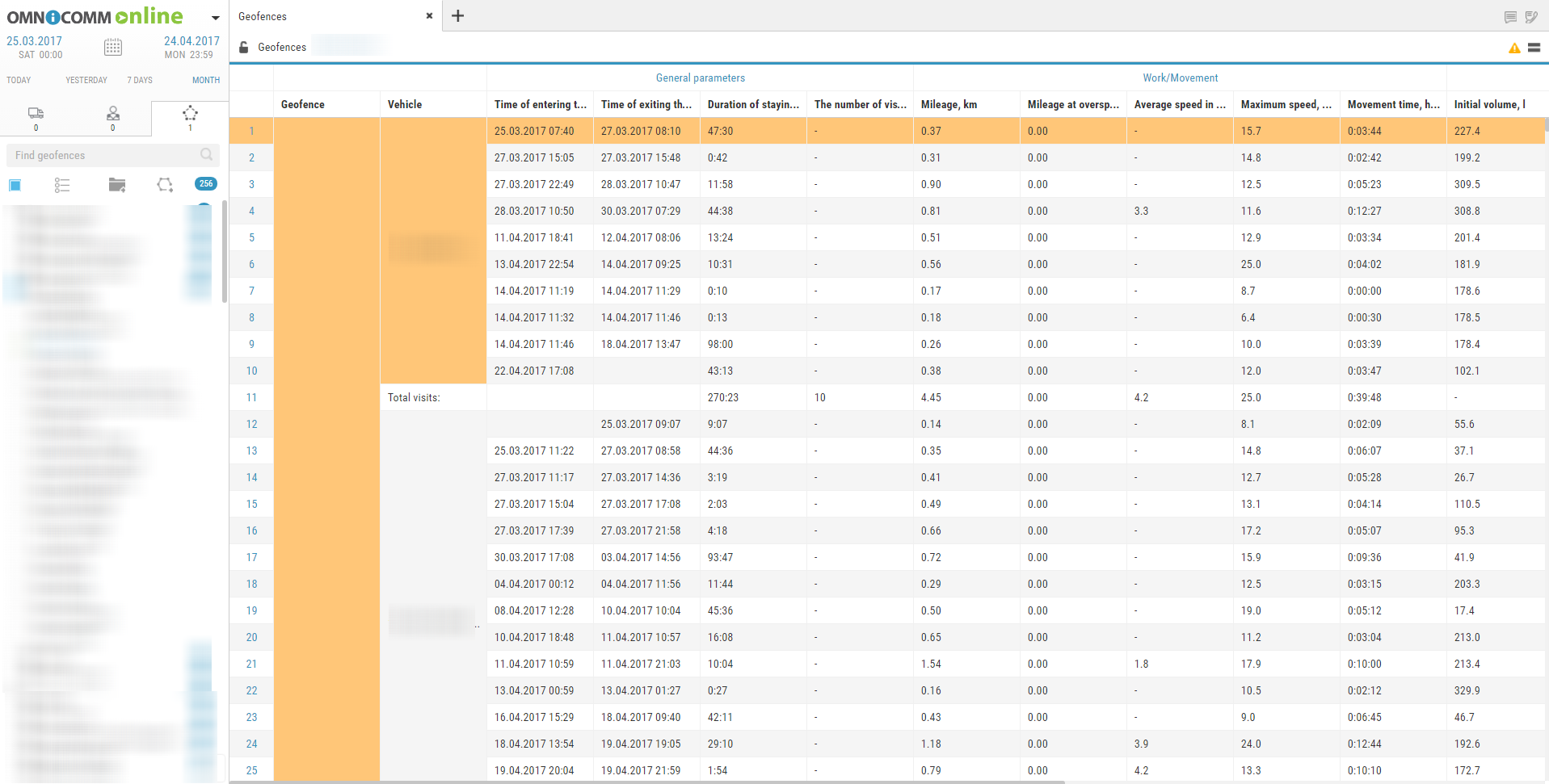
This report contains the following information on the VH:
•VH name is a registration number of name the VH.
•Geofence is a geofence name.
•Time of entrace to geofence is date and time of entrace to thegeofence ddmmyyyy hh:mm
•Time of exit from the geofence is date and time of exit from the geofence of ddmmyyyy hh:mm
•Duration of stay is time during which the VH was in the geofence, hh:mm
•Number of visits is a number VH geofence entries within the selected period of time
•Mileage, km is a mileage of the VH in the geofence
•Speeding mileage, km is a VH speeding mileage in the geofence
•Average speed in movement, (km/h) is an average VH motion speed in the geofence
•Movement time is time during which the VH was moving in the geofence, hh:mm:ss
•Downtime is time during which the VH's downtime was identified when the VH was in the geofence, hh:mm:ss
•Downtime, (hh: mm: ss) is time within a period which will be calculated using a formula:
“Downtime” = “time of operation under rated load” – “idle time within period” – “overultimate load time”
•General consumption, l is general consumption of the VH when the VH is in the geofence
•Volume of refuellings, l is a volume of fuel refuelled when the VH is in the geofence
•Fuel volume drained, l is volume of fuel drained when the VH is in the geofence
Calculation of the VH presence in the geofence:
— If at the period the VH was in the geofence, duration of the stay in the geofence shall be calculated from the period start and to the moment of escape from the geofence or end of period depending on which of these events took place earlier. I.e. if a moment of exit from the geofence is earlier than an end of period, the duration shall be calculated from the period start to the moment of exit from the geofence. In “Time of entrance to the geofence” field the dash “-” wil be displayed.
— If at the period end the VH was in the geofence, duration of the stay in the geofence shall be calculated from the entry to the geofence or a period start depending on which of these events took place later and till the period end. If the moment of entry to the geofence is later, that the period start, duration of stay shall be calculated from the moment of entry to the geofence to the period end. In the field “Time of entry to the geofence” dash “-” shall be displayed.
— If the period end is greater than the current time, when calculating duration the current time instead of period end shall be used.
•Treated area, ha
•Productivity, ha/hr
•Rated consumption, l/ha
Log
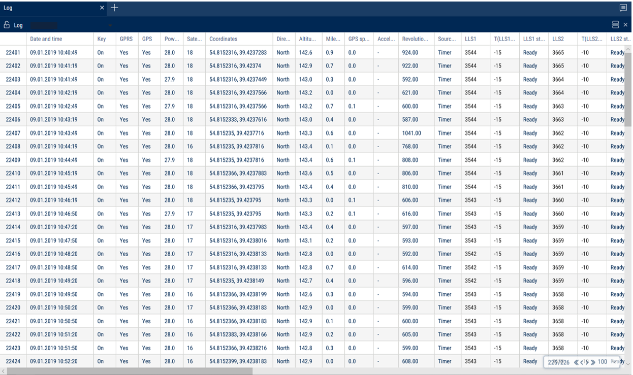
Report “Log” allows review of “raw” data received by Omnicomm Online from the terminals.
1. Select a VH.
2. Please select a period of time for report generation.
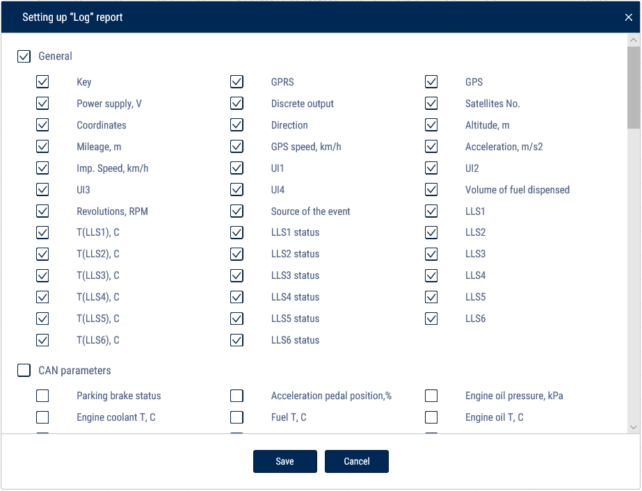
Select information to be displayed in the report by pressing the right mouse button and choosing “Report settings”:
Report contains the following information on the selected vehicle:
The “General” section:
•Date and time is date and time of the event.
•Ignition is a state of ignition at the certain moment (On or Off).
•GPRS is presence or absence of GPRS at the given moment.
•GPS is presence or absence of data from GPS at the given moment.
•Number of satellites is a number of satellites based on which GPS data were determined at the given moment.
•Coordinates are coordinates (latitude and longitude) of the vehicle location at the given moment, measured in degrees or message “Connection of on-board equipment” at the moment of connection of the terminal with the Communicaton server. If the number of satellites for coordinates determination is less than 4, coordinates are displayed grey.
•Direction is direction of vehicle motion (N (North); NE (Northeast); E (East); SE (Southeast); S (South); SW (Southwest); W (West); NE (Northwest)).
•Height, (m) is altitude of the VH above the sea level.
•Mileage, (km) is path travelled by the car.
•Speed GPS, (km/h) is VH speed at the given moment determined by GPS.
•Speed pulse is a value of speed in kilometers per hour by the data from the regular meter or read from the CAN-bus depending on the speed imput settings on Omnicomm online software.
•Acceleration (m/s2) is a value of VH acceleration.
•Revolutions means level of revolutions per minute by data from tachometer or read from the CAN-bus depending from the settings on Omnicomm Configurator software.
•ON voltage is voltage of VH onboard network (V). For Omnicomm Profi in case of operation from reserve battery, voltage of reserve battery (RB).
•Data on CAN-bus.
•Values from four universal inputs.
•LLS1, LLS2, LLS3, LLS4, LLS5, LLS6 is code from the first to the sixth by LLS fuel level sensor. If there is no calibration table for this sensor, “0” is displayed grey.
•T (LLS1), T (LLS2), T (LLS3), T (LLS4), T (LLS5), T (LLS6) is temperature (C°) output from the first to the sixth sensor of LLS fuel level sensor. If there is no calibration table for the sensor, “0” is displayed grey.
•LLS1 status, LLS2 status, LLS3 status, LLS4 status, LLS5 status, LLS6 status:
— Ready, the sensor is connected and shows correct data
— No, the sensor is not connected or adaptive data collection in the Terminal is on
— Error, the sensor is connected, but shows incorrect data
— Not ready, the sensor is ready, but power supply to the sensor started less than 15 seconds ago
•“Volume of fuel dispensing”, (l) (for fuel tanker only) is volume of fuel dispensed through fuel nozzle.
•“The source of event” is condition for creation of an event by the Terminal (turning point, timer)
The “CAN parameters” section:
•Parking brake status
•Accelerator pedal position, %
•Engine oil pressure, kPa
•Engine coolant temperature, °C
•Fuel temperature, °C
•Engine oil temperature, °C
•Daily fuel consumption, l
•Instantaneous fuel economy, km/l
•Engine rpm
•Daily mileage, km
•Total mileage, km
•Total time of engine operation, h
•Overall fuel consumption, l
•Position of the service brake pedal
•Clutch pedal position
•Cruise Control status
•Axle load, kg
•Status of the service brake pedal
•Status of the clutch pedal
•Mileage before the next maintenance, km
•Engine operation time before the next
•Maintenance, h Instantaneous speed, km/h
•Doors status
•Seatbelts status
•CAN rpm
•OBDII. Mileage after error reset, km
•OBDII. Time after error reset, h
•OBDII. Fuel level, %
•OBDII. VIN ТС
•OBDII. Check Engine error
The “iQFreeze” section:
•CHU temperature
•Refrigerator temperature in section 2
•Refrigerator temperature in section 3
•Set temperature
•Set temperature 2
•Set temperature 3
•Ambient temperature
•Coolant temperature
•Engine rpm
•Compressor configuration
•System status
•Door status
•Battery voltage
•Battery current
•Operating hours from the engine
•Operating hours from the onboard network
•Unit serial number
•Trailer serial number
•Number of errors
•Code of the main error
•2nd, 3rd, 4th, 5th, 6th level errors
•IQFreeze serial number
•IQFreeze firmware version
•IQFreeze Bluetooth name
•Unit type
•Connection to CHU
•Digital inputs No.1, No.2
The “Tire Pressure Monitoring” section:
•Wheel number: current pressure, kPa
•Wheel number: current temperature
•Wheel number: wheel sensor connection status
•Wheel number: sensor battery charge
•Wheel number: reason for sending. Possible values: recurrent sending, air leakage, rapid air leakage, tire re-inflated
The “Safe Driving” section:
•Violation source
•Speed threshold, km/h
•RPM threshold, rpm
•Acceleration threshold, m/s2
•Lateral acceleration threshold, m/s2
•Braking acceleration threshold, m/s2
•Vertical acceleration threshold, m/s2
•Acceleration along the X-axis, m/s2
•Acceleration along the Y-axis, m/s2
•Acceleration along the Z-axis, m/s2
•Accelerometer status
The “GenComm generators” section:
•Oil pressure, kPa
•Coolant temperature, °C
•Voltage of the charging generator, V
•Frequency of the output voltage, Hz
•L1, L2, L3 voltage, V
•L1-L2, L2-L3, L1-L3 line voltages, V
•L1, L2, L3 currents, A
•L1, L2, L3 active power, W
•L1, L2, L3 total powers, kVA
•L1, L2, L3 reactive power, kVAr
•Power factor
•Motor hours
•Total energy generated, kW⋅h
•Fuel volume, %
•Charge current, A
•Battery voltage, V
•Revolutions, rpm
•Diesel status
•Status of the diesel-driven generator set
Optional parameters:
•FLS PMP-201, Struna+
The “Display of technological operation parameters” section:
“Type of equipment” - select the type of equipment for which to display technological parameters.
Possible options: TG series Grader and WX200, TX210 Excavator.
For the TG series Grader the following parameters are displayed:
•ICE. Coolant temperature, °C
•ICE. Charge air temperature, °C
•ICE. Oil pressure, bar
•ICE. Charge air pressure, bar
•ICE. Crankshaft rotation speed, rpm
•Gearbox. Oil pressure in the lubrication system, bar
•Gearbox. Oil pressure in torque converter, bar
•Gearbox. Error codes
•Gearbox. Oil temperature
•Gearbox. Speed, km/h
•Gearbox. Number of the current gear
•Gearbox. Operating mode
•Electrical system. Voltage, V
•ICE. Oil temperature, °C
•ICE. Fuel rail pressure, bar
•ICE. Error codes
•Hydraulic system. Oil temperature, °C
•Hydraulic system. Oil pressure, bar
To change the width of a column, select the border of the column and drag it while holding the left button of the mouse.
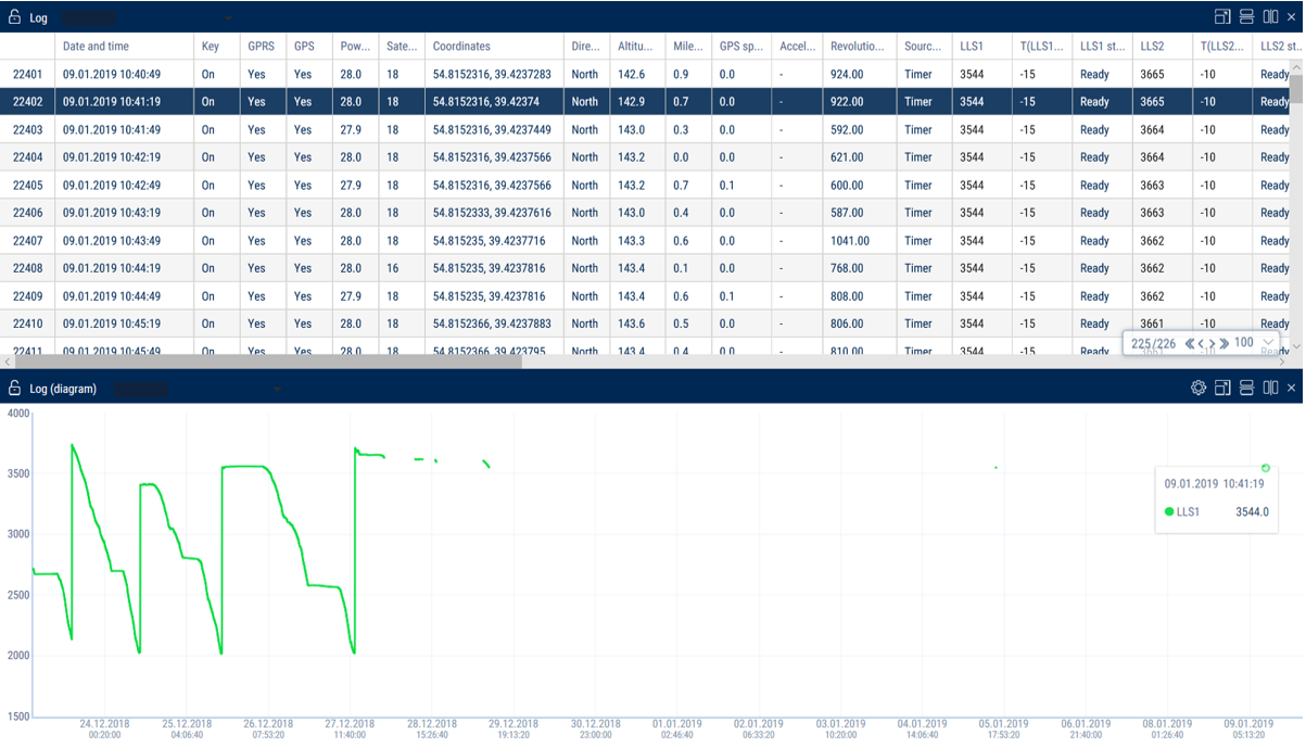
Display parameters as a diagram
1. Select a column with a parameter
2. Right-click and select “Display as a diagram”
When a point is selected on the graph, the corresponding row in the “Log” report is automatically highlighted.
Hiding rows with parameter values that are equal to zero or missing
1. Select a column that contains rows with valid and missing parameter values.
2. Right-click and select “Hide rows with empty cells”
3. Rows with missing values will be hidden in the report. To show rows again, right-click and select “Reset all filters”.
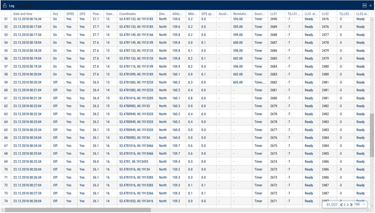
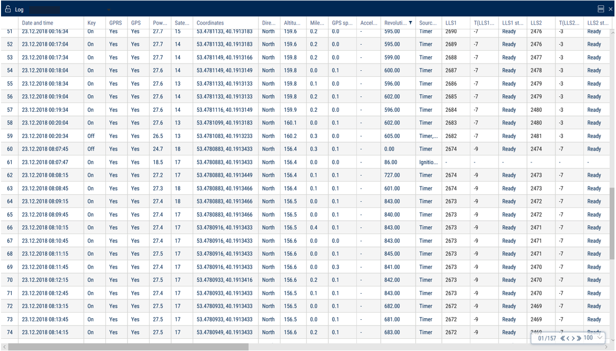
Let's take the column with the parameter “Revolutions” as an example.
To hide the empty cells:
After the empty cells have been hidden:
Parameters for which the option of hiding rows does not apply:
•Row number
•Date and time
•Ignition key position
•GSM connection
•GPS data validity
•Digital output status
•Event source
•Sensor level code
•Sensor temperature
•Sensor readiness
•Coordinates
•GPS speed
•Pulse speed
•Dispensed fuel volume
•Power
•Battery charge percentage
•Direction
•Number of satellites
•Height
•Mileage
•UI1…UI4
Drivers registration
1.Select a vehicle or a driver.
2.Please select a period of time for report generation.
3.Press “Add report button” and select “Driver registration”.
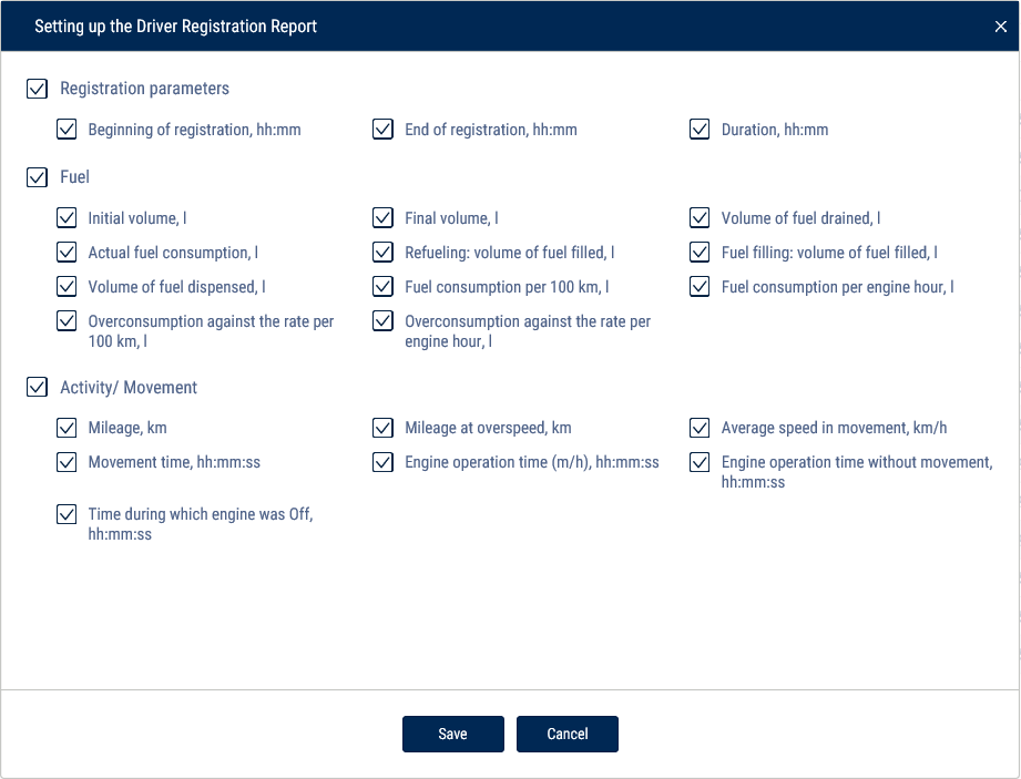
To set up the report, press the right mouse button and select “Report settings”:
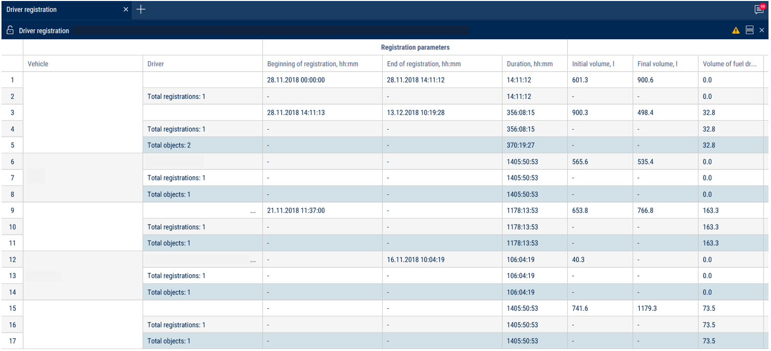
This report contains the following information:
•VH name is a registration number of name the VH.
•Driver, last name and first name of the driver assigned to VH.
•Registration start is date and time of the driver assignment to the VH. If “-” is specified, assignment of the driver to this VH was performed before the selected period of the report generation.
•Deassignment is date and time of the driver deassignment from the VH. If “-” is specified, deassigment of the driver from the VH is scheduled later than end of the selected period of report generation.
•Duration, hh: mm: ss is duration of driver assignment to the VH within the selected period.
•Initial volume, (l)
•Final volume, (l)
•Actual consumption during the period, (l)
•Refuellings volume, (l)
•Fuel volume drained, (l)
•Consumption per 100 km, (l)
Description of the fuel parameters calculation is given in the Appendix.
Photographs
1.Select one or several VH.
2.Select a period of time.
3.Press “Add report” button and select “Photographs”.
Photographs are related to “Track” report. When opening two reports and selecting “Photographs” line of the report the place on the map where the photographs were taken is highlighted automatically and a help message with information on VH is displayed (dates, time, VH speed, address, mileage and state of ignition).
To save a photograph press the right mouse button on the photograph and select “Save image as”.
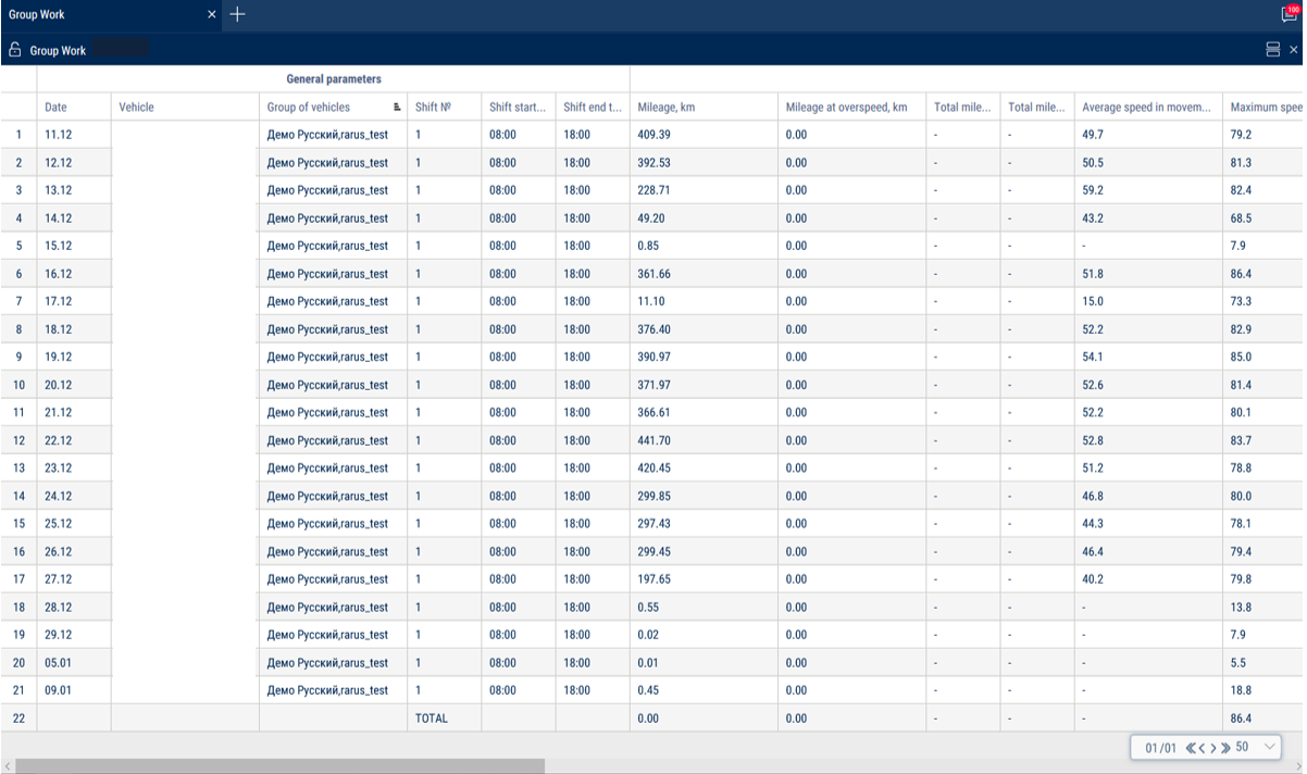
Group work
1.Please select one or several VH or drivers.
2.Please select a period of time for report generation.
3.Press “Add report” button and select “Group work”.
Set up the shifts schedule by pressing the right mouse button and selecting “Shifts setup”. The window will open, in which you will see a line with schedule to be added.
In the fields “Shift 1 start”, “Shift 2 start”, “Shift 3 start”, “Shift 3 start” enter the time in hh:mm format, from which the start of the first, second, third and fourth shifts will be accounted.
In the fields “Shift 1 end», “Shift 2 end”, “Shift end 4” enter the time in hh:mm format starting from which the end of shift will be accounted.
In column “Current” select the checkbox. Press “Save” button.
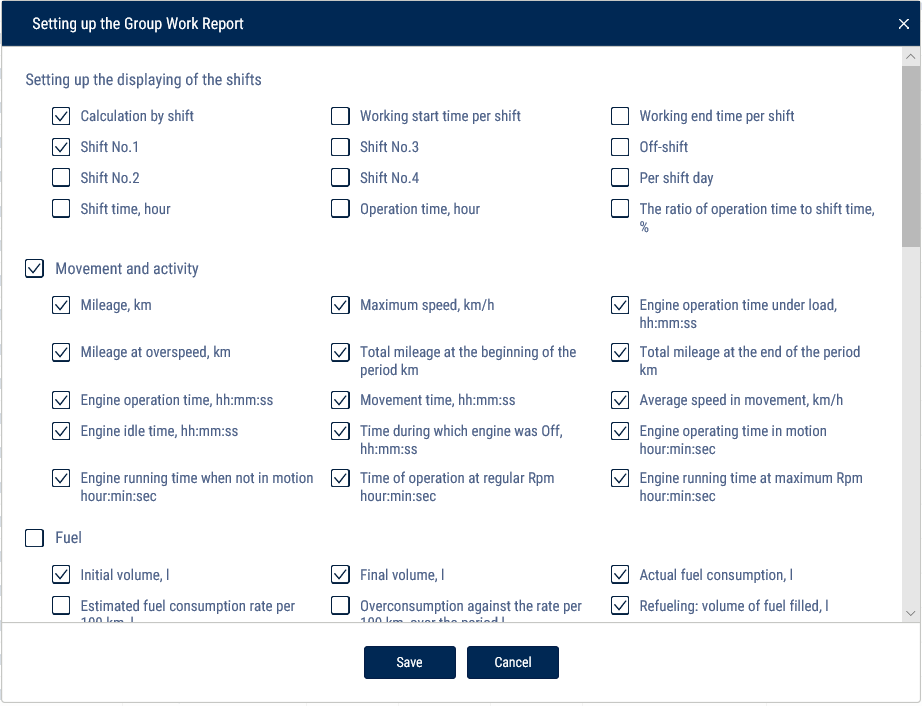
Select the information to be displayed in the report by pressing the right mouse button and choosing “Report settings”:
In the “Shift display settings” section:
•Payment by shifts
•Start of work during a shift
•End of work during a shift
•Shift no. 1, 2, 3, 4
•Off-shift
•Per shift day
In the “Movement and Operation” section:
•Mileage, km
•Mileage with speeding, km
•Engine operation time, hh:mm:ss
•Time of idle engine operation, hh:mm:ss
•Time of engine operation without movement, hh:mm:ss
•Maximum speed, km/h
•Mileage at the beginning of the period, km
•Mileage at the end of the period
•Time of movement, hh:mm:ss
•Time with engine turned off, hh:mm:ss
•Time of engine operation at regular rpm, hh:mm:ss
•Time of engine operation under load, hh:mm:ss
•Average speed in movement, km/h
•Time of engine operation at maximum rpm, hh:mm:ss
In the “Fuel” section (main tank):
•Initial volume, l
•Final volume, l
•Actual consumption, l
•Estimated consumption rate per 100 km, l
•Overconsumption against the rate per 100 km, l
•Refueling volume, l
•Draining volume, l
•Filling volume, l
•Dispensed fuel volume, l
•Actual consumption per 100 km, l
•Actual consumption per engine hour, l
•Actual consumption per hour of engine operation, l
•Overconsumption against the rate per 1 hour of engine operation, l
•Actual consumption per hour of engine operation in movement, l
•Actual consumption per hour of engine operation without movement, l
•Possible draining / Excess, l
•Minimum volume, l
•Maximum volume, l
•Actual consumption per 100 km in movement, l
•Actual consumption in movement, l
•Actual consumption without movement, l
•Consumption norm per 100 km, l
•Deviation from the norm per 100 km, l
•Actual consumption during the time of engine operation, l
•Consumption norm per hour of engine operation
•Estimated consumption as per norm per hour of engine operation, l
•Deviation from the norm per hour of engine operation, %
In the “Fuel” section (auxiliary tank):
•Initial volume, l
•Final volume, l
•Actual consumption, l
•Refueling volume, l
•Draining volume, l
•Minimum volume, l
•Maximum volume, l
•Actual consumption per 100 km, l
In the “Auxiliary Equipment work” section:
•Maximum value during the period
•Minimum value during the period
•Total value during the period
•Mileage with auxiliary equipment in operation, km
•Time of operation, hour:min:sec
•Idle time, hour:min:sec
•Time of operation above the allowable value
•Time of operation below the allowable value
•Consumption with auxiliary equipment turned on, l
•Consumption with auxiliary equipment turned on per motor hour, l
•Consumption with auxiliary equipment turned on per 100 km, l
In the “Meter readings (CAN bus data)” section:
•Engine hour meter reading, hour:min
•Fuel consumption meter reading, l
•CAN odometer reading at the beginning of the period/shift, km
•CAN odometer reading at the end of the period/shift, km
In the “Meter readings before maintenance (from CAN bus)” section:
•Mileage before Maintenance service, km
•Engine hours before Maintenance service, hour
In the “CAN data during the report period” section:
•Mileage, km
•Engine hours, hour:min
•Fuel consumption, l
“Report Object Groups” - enable to display the names of groups that the vehicles belong to.

