Work
Engine Revolutions
- Select a VH.
- Please select a period of time for report generation.
- Press the button “Add report” and select “Engine revolutions”.
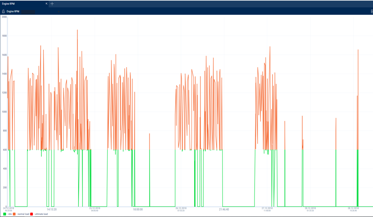
In the program window the report on VH engine revolutions will display.
If a period between neighboring events recorded in the register is shorter than 8 minutes, ignition turn-off won't be displayed on the revolutions diagram.
The following color designations are used in the report:
•Green diagram means level of idle revolutions of the VH engine. The level of idle revolutions shall be set in the VH profie.
•Yellow diagram means normal load, level of engine revolutions is greater than level idle revolutions and less than level of ultimate revolutions. The level of idle revolutions and engine RPM level limit shal be set in the VH profile.
•Red diagram means ultimate load, level of revolutions greater than ultimate engine speed. The engine RPM level limit is set in teh VH profile.
If necessary, increase the diagram scale. Select a part of the diagram, which shall be increased pressing the left mouse button continuously.
To return to the original diagram scale, refresh the report.
To display a pop-up tip with an accurate value of engine RPM select a required spot in the diagram.
Revolutions values from 0.0 to 1.0 mean there is no connection to revolutions sensor, please contact specialists who installed on-board equipment. In case the values exceed 10 000 RPM, contact the specialists who installed on-board equipment, in order to get the “Correction coefficient of revolutions sensor” corrected.
Onboard Voltage
- Select a VH.
- Please select a period of time for report generation.
- Press the button “Add report” and select “Onboard voltage”.
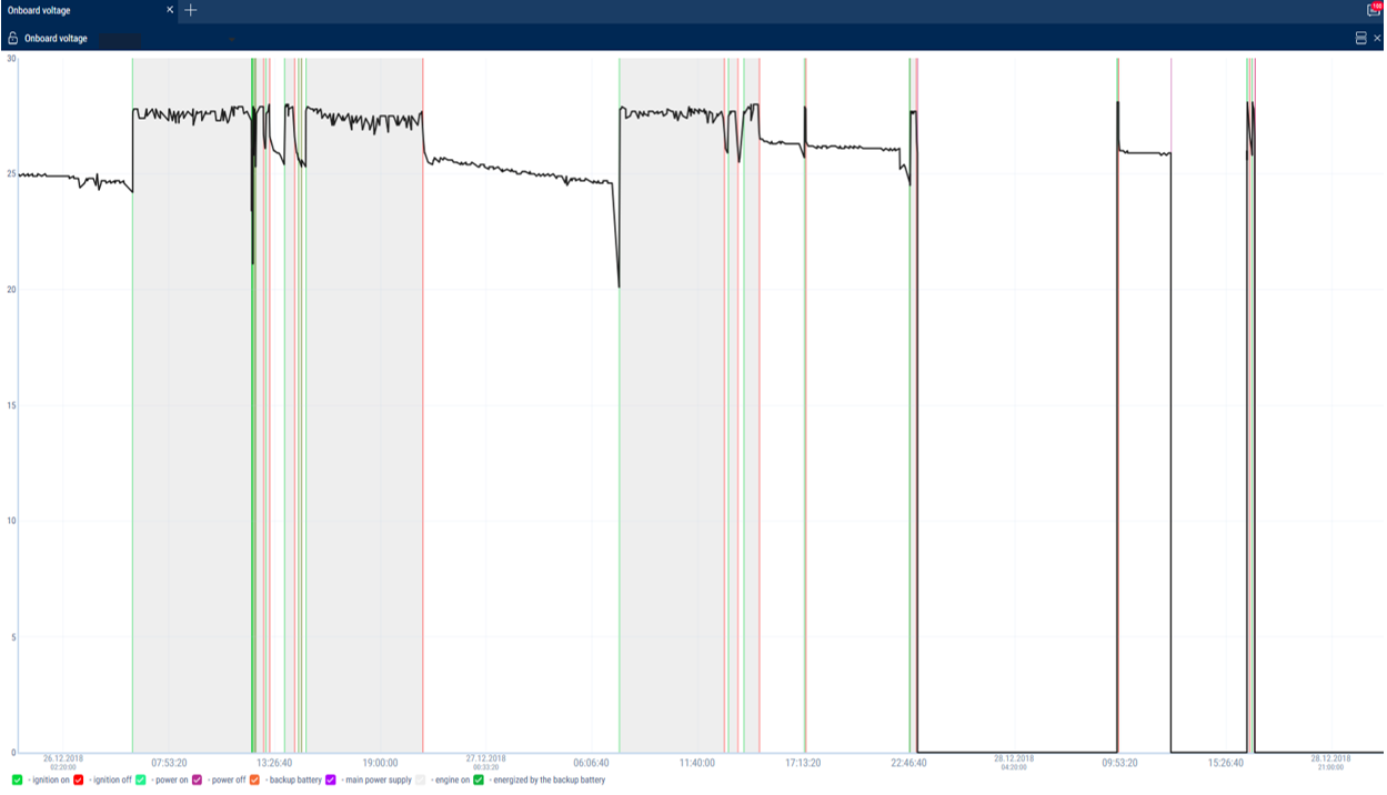
In the program window the report with data on onboard voltage of VH for the selected period will open.
Select the information to be displayed in the legend:
If time between the neighboring events is greater than the double value of data collection timer, the value of power voltage for this period shall be displayed equal to zero.
To display a pop-up tip with an accurate value of VH on-board network voltage select a required spot in the diagram with the mouse pointer.
Auxiliary Equipment Operation
One report can display up to four diagrams on operation of auxiliary equipment (for Omnicomm Profi Terminals).
- Select a VH.
- Please select a period of time for report generation.
- Press the button “Add report” and select “Auxiliary equipment”.
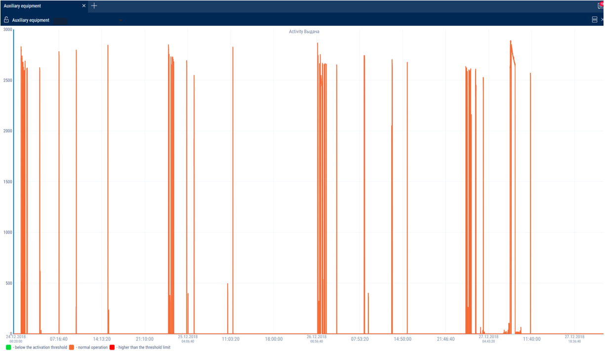
In the program window the report on operation of additional equipment will display.
The following color designations are used in the report:
- Red diagram means value higher than the ultimate value set in the VH profile.
- Green diagram means that the value does not exceed ultimate value set in the VH profile.
To display a pop-up tip with an accurate value of fuel volume select a required spot in the diagram with a mouse pointer.


